
Recently on a couple of occasions the oil light stayed on after starting the engine. A quick blip on the throttle was usually sufficient to get the light to go out. Still it was a bit worrying so I decided to change the oil and filter but not before I tested the oil pressure switch, just in case.
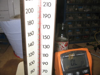
The switch is normally closed and using a sphygmomanometer I measured about 210mmHg (4.2psi) when it opened. So no
problem there then.
I flushed the engine with some STP agent then changed the filter and refilled with my usual 10/40 semi-synth.
I put in about 4 litres expecting to have to top it up once it had settled. The dipstick
showed oil about 0.5cm above the max. I started the engine, the oil light went out and I let
it run for a minute or so. The oil level was still well above the maximum so I went to
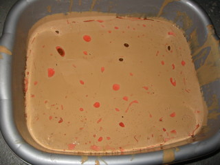
drain some off. Unscrewing the drain plug allowed some oil to come out but then it stopped!
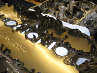
Then I saw something oozing out like a lump of soft jelly which plopped into the measuring
jug I was using to catch the oil. This continued for several minutes until the oil started
to run freely. Taking out half a litre made no difference to the level on the dipstick!?!?
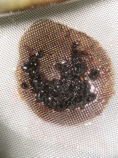
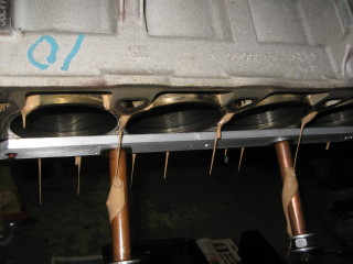
Time to drain the sump again! Using a flour sieve you can see the lumps of jelly which
came out. My problems didn't stop there of course. I had left it draining overnight and when I
got back to it, it was still dripping.
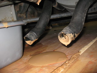
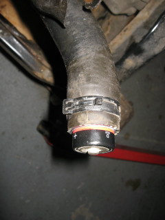
There was something distinctly watery about these drips. I pressurised the header tank using
my brake bleeding kit and coolant started pouring out of the sump.
"Hmmm, I don't think that should happen" I thought!
For some time now the MG has exhibited vague signs of possible HGF (Head Gasket Failure).
Erratic coolant level; scum in the header tank. But never any significant oil/coolant emulsion.
On long runs everything was perfect; coolant ok, oil lovely and clear, only when it was left standing
for several days with just the occasional short trip were the problems evident.
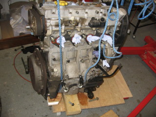
The engine is still in its original state and even though it has only done about 56k miles it
is nearly 10 years old. According to the service schedule, the cam belts should be changed
every 60k or 4 years whichever comes first. Time for a major service at least. But, with the
possibility of blocked or narrowed water / oil galleries, it would be sensible to remove the engine
and overhaul it.
Also, the last MOT listed a couple of advisories: slight play in a front off side suspension joint,
and slight corrosion in all (yes, all) brake pipes. The rear brake pipes should be easier to replace
if the engine was missing and so ...

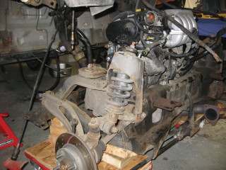
Decision made - engine is coming out!!
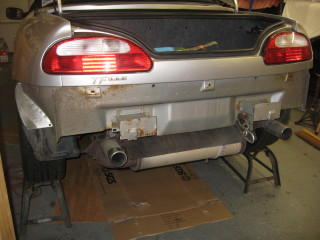
Back end still up on ramps.

Disconnect coolant hoses at front of car and drain. There is some coolant in the bowl, honest!
However it looks like the cooling system is in a right mess and the only indication was a bit of
scum in the header tank!
Remove rear valance.

Remove silencer and cat. (At this point you can make it more interesting by waiting until
you are holding the unattached silencer and cat before unscrewing the lambda sensor!)

Remove silencer heat shield. Four 6mm set screws soaked overnight in PlusGas. Ruined the
bolt heads but got them out without shearing (DYP10015).
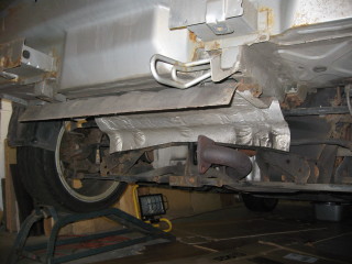
This should give the maximum clearance and hence the minimum lift required for the car body.
I can also remove the coolant hoses near the engine.
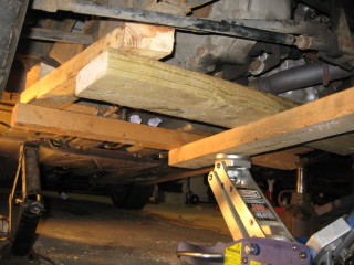
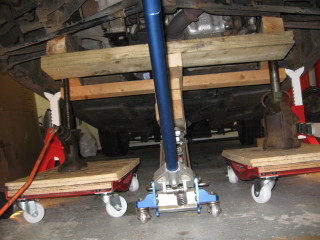
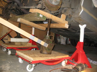
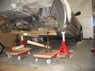
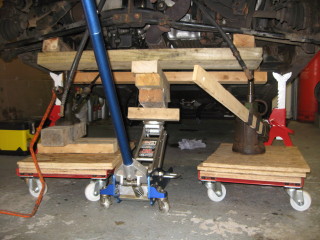
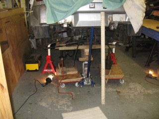
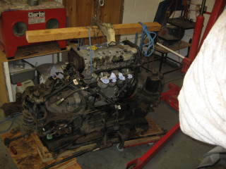
Build wooden cradle to support engine and subframe while it is lowered onto a pair of wheel
dollies.
Drain gearbox oil. Got 2.2 litres of good clean oil. Good news for once.
Move to the front of the car to remove valance for scratch removal and access/inspection.
Also to remove radiator for flushing.
Removal of the front valance was nearly easy. Five screws in the bonnet locking panel, two torx
screws in the bumper armatures, two screws at either side in the wheel arch liners and last but by
no means least, two screws at either side fastening the valence to the wing.
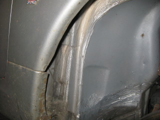
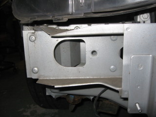
Decided to remove the liner (a) to get easy access to those screws and (b) to see what state the car
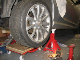
was in behind the liner. Jack up the car and remove the road wheel. Three scrivets and a screw are all
that need to be removed. Ruined the scrivets (DBP5563) but got the screw out ok - o/s liner pulls off (it's just
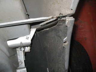
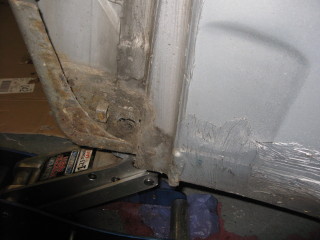
thinnish plastic). Metal looks surprisingly good. There is a crud collection point where the rear of
the wing meets the front of the sill. Wheel back on and repeat the process on the n/s. Used PlusGas
this time and all the fasteners came off easily. Wheel replaced and car back on the ground.
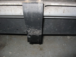
There is a tie strap underneath the valence in the middle which is not mentioned in the workshop
manual. Two more screws to remove. The o/s spotlight was half full of water so I used that to rinse
my hair while getting the tie strap off. Very refreshing!
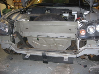
Now I can roll the valence forward to gain access to the spotlights and unplug them. Finally! The
valence is off.
At this point I find the o/s armature (DPE100431) is bent and there is a hole in the o/s spotlight
(XBJ105500, the n/s lamp is XBJ105510).
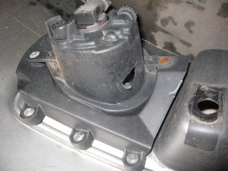
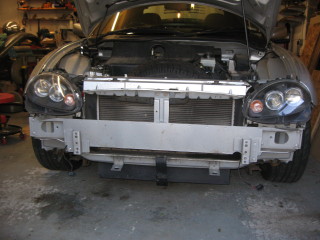
Now to get the radiator out.
Remove the armature.

Disconnect the bonnet release cable and remove the bonnet locking panel.

I disconnected the top and bottom hoses since each has two clips holding them in place underneath
the spare wheel well.

Unplug the fan and lift out the radiator and leave it to drain the sludge into a bowl.
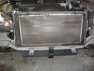
Bodywork doesn't look too shabby, just a few rust spots to tidy up. Nothing major (yet!).
That should be all I need to do at the front for now so push the car up close to the garage door
to give me as much space as possible at the rear.

The work around the engine is based on the MG TF Workshop Manual from which I created a check list.
There are some items in the manual for which I had to be a little creative as well as
borrowing ideas used by other MG owners.
For example, item 1: "Position vehicle on a 2 post ramp" - t'would be good if I could.
Also, if CJJ (www.the-t-bar.com) can do it on the drive in front of his house, then I can at least
give it a go in my nice warm garage.

The items in blue are deviations from the manual for my own purposes.
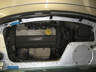
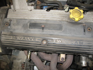
Remove battery having lowered the door windows
Remove T-bar first for easier access, remove insulating mat, remove engine cover.
Remove the two cross bracing bars noting that they are different lengths.
Remove oil filler and dipstick assembly as this is a high point on the engine.
Drain cooling system. (already done)

Release clip and disconnect hose from coolant outlet elbow on cylinder head.
Release 3 clips and disconnect coolant hose assembly between coolant outlet elbow, heater coolant
  rail and feed hose to expansion tank.
Release clip and disconnect hose from coolant rail.
Release clips securing air intake hose between air cleaner and throttle body, remove intake hose.
Release clip and evaporative emission hose from throttle body.
Disconnect throttle cable from abutment bracket and throttle cam.
Release throttle cable from inlet manifold clip and position cable aside.
Position absorbent cloth around fuel filter, loosen union to relieve fuel pressure, retighten union
  to 30 Nm.
Release quick release connector securing fuel hose to fuel filter outlet pipe.
Release quick release connector securing fuel return hose to fuel return pipe.
Depress locking collar and release brake servo pipe from inlet manifold.
Release clip and coolant hose from inlet manifold.
Remove 2 bolts securing expansion tank to body, raise expansion tank, release clip and disconnect
  hose from expansion tank.
Remove expansion tank
Remove nut and disconnect battery lead from starter motor solenoid.
Disconnect Lucar connector from starter motor solenoid.
Release clip securing battery lead to clutch slave cylinder mounting bracket
Remove cover and main fuse from fuse holder. Remove screw securing fuse holder to body, position
  fuse holder aside.
Remove inner bolt and loosen outer bolt securing ECM mounting bracket.
Disconnect multiplugs from ECM.
Disconnect engine harness and relay unit multiplugs.
Remove ECM
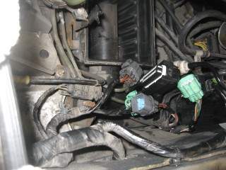
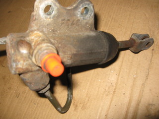
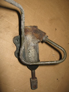
Disconnect multiplug from emission canister purge control valve.
Remove 'R’ clip, washer and clevis pin securing clutch slave cylinder push rod to release lever and
  remove push rod.
Remove 2 bolts securing clutch slave cylinder to mounting bracket, position slave cylinder aside.
Raise vehicle using axle stands under rear jacking points.
Drain gearbox oil (already done)
Remove heat shield above rear silencer (already done)
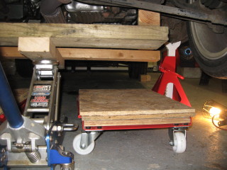
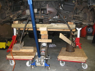
Remove road wheels.
Used this opportunity to do a trial lift to see if I could get the boot high enough.
The trolley jack did the initial lift then I used two old jacks, one at each side of the table.
These did the final lifting and got the boot to 930mm off the floor with some spare capacity.
This should be sufficient to clear the engine/subframe supported on the table and dollies.
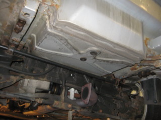
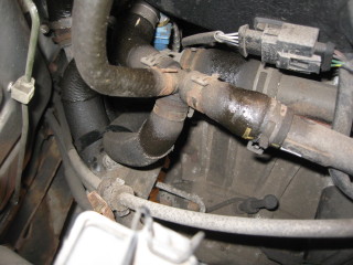
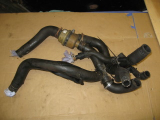
Release clips and disconnect coolant hoses from coolant rail underneath vehicle.
Release clips and disconnect heater hoses from underneath vehicle. What a struggle that was! The quick
release connectors were seized and the hoses did not want to come off.
Remove cable tie securing battery cable to coolant hose, position battery cable aside.
Remove bolts securing LH and RH ABS sensors to hubs, release sensors and collect sensor spacers.
Release LH and RH ABS sensor lead grommets and sensor leads into brackets and clips on each subframe
  turret and upper suspension arms.
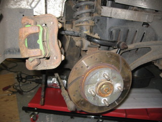
Remove bolts securing LH and RH brake calipers to hubs. Release calipers and tie aside.
Note that I also disconnected the handbrake cables from the caliper because I thought it might help
putting the calipers out of the way.
Remove bolt securing engine earth lead to cylinder block, position earth lead aside. This was quite
awkward. I could only get enough access using an open ended spanner and I ended up linking two spanners
together.
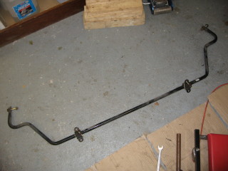
Remove 4 nuts securing anti-roll bar clamps and rubber mountings to subframe. Collect clamps and rubber
  mountings.
Remove nuts and bolts securing LH and RH anti-roll bar links to trailing arms and remove anti-roll bar.
Remove and discard clips securing selector cables to gearbox abutment brackets.
Note that these clips (UYC10006) are over £8 to replace new (£5.40 from Mike Satur) but as mine came out
unscathed they will be going back.
Release selector cables from selector linkage and position cables aside (mine are breaking up and will
need replacing hopefully without buying a complete cable).
Just a couple of observations while I was under the car:
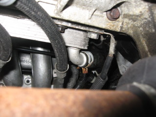
One of the gaiters on the end of the gear select cables is disintegrating so I will be looking into
replacing that - hopefully without replacing the whole cable.
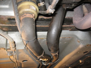
The connector to the clutch slave flexible looks as though it will foul the subframe as it is lowered.
I will be disconnecting the pipes at that point.
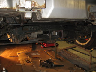
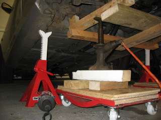
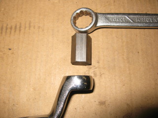
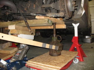
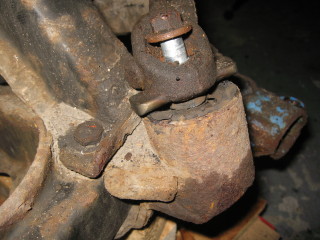
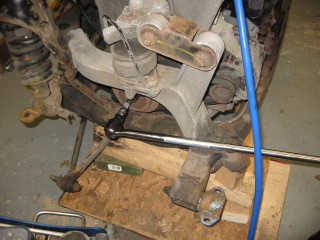
Remove each subframe mounting bolt in turn and ensure that they are all free and can be removed easily.
This was surprisingly easy for 6 bolts holding the rear mountings. The 4 front mounting bolts were all
somewhat rusty and one of them rounded off with the required 10mm socket. I did get it off by hammering
a 3/8 socket on and using that. Four new bolts required.
Support the subframe on the wooden platform and raise the car to the desired height which was about 40"
to the bottom of the boot floor.
Remove 4 front bolts and 6 rear bolts securing subframe mountings to body.
Collect anti-roll bar mounting brackets.
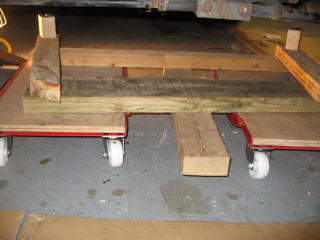
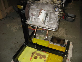
Put the wheel dollies into position
Carefully lower the platform and guide engine and subframe from engine compartment onto the dollies.
Ensure that subframe/engine assembly is positioned securely on engine table and remove the jack.
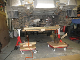
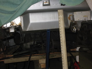
Ensure there is sufficient clearance between top of engine and car body.
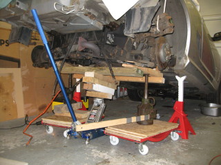
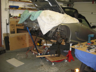
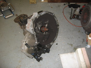
Roll the engine/subframe clear of the car.
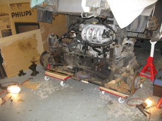
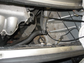
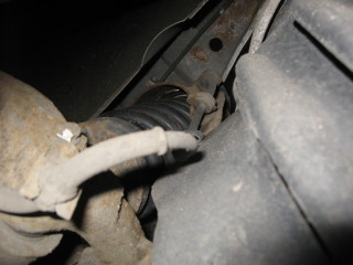
There was ample clearance above the engine high point (rocker cover oil filler cap) - about 3 inches.
This means that I can lower the car body an inch or two if I want.

Lowering was not as straightforward as I have just made it seem.
There is an air intake pipe which lies along the rear of the subframe. This had to be removed as it
was being crushed against the inlet manifold. It is held in place by a broad tie-wrap and I had to raise
the subframe in order to cut it and get the pipe out of the way. Fortunately I had already taken the
bottom of the air filter box off to get better access.
Then there was a near disaster in the final few inches when the engine cleared an obstruction which must
have been keeping the engine/subframe fairly level from left to right. At this point the table was only
supported on the trolley jack at what I thought was a balance point. On passing the obstruction the
whole assembly tilted alarmingly to the left. Fortunately the car stayed on the stands and the table
didn't slip off the jack. Very lucky. I could finish lowering without damaging anything or anyone.

WATCH THE VIDEO AND LEARN FROM MY MISTAKES!!
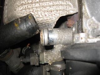
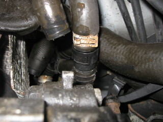
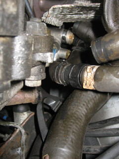
The only damage I could find was a skinned water pipe - part of a spaghetti junction which, although
disconnected, I left in situ. Perhaps it was this that provided the obstruction.
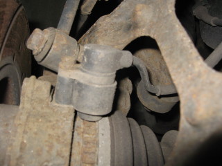
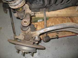
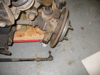
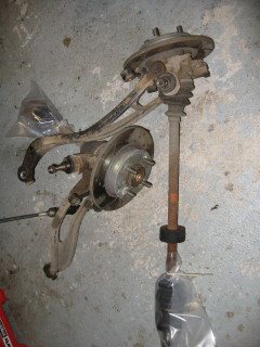
Remove nut and bolt securing trailing arm to trailing arm bush.
Remove bolt securing lower link to rear hub.
Remove nut securing track control rod to hub.
Release track control rod taper joint from hub using an ordinary ball joint separator (OBJS).
Remove and discard lock nut securing ball joint to upper suspension arm.
Fit slave nut to ball joint threads, position the OBJS and release ball joint taper from upper suspension arm.
Remove the OBJS and slave nut.
Release drive shaft inner joint from gearbox with the judicious use of a crowbar.
Remove hub assembly and drive shaft.
Remove and discard circlip from drive shaft.
Repeat operations for opposite hub assembly.
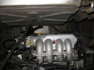
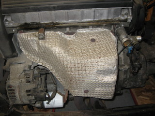
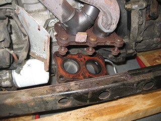
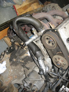
Remove nut and 2 speed bolts securing heat shield to cylinder head and exhaust manifold, remove heat shield.
Release lambda sensor multiplug from bracket at rear of cylinder head and disconnect multiplug by rotating it
45 degrees.
Release lambda sensor harness from clip on cylinder block bracket
Remove 6 nuts securing front pipe to exhaust manifold.
Release front pipe from exhaust manifold and support rubber, remove front pipe, remove and discard gasket.
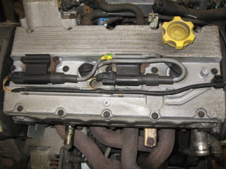
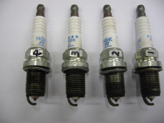
Remove the cover from the top of the engine.
Remove the coils and HT leads. Two of the leads seemed to have glued themselves to the cavity above the spark
plug - perhaps a sign that things were getting a bit hot?
Remove the plugs. All the plugs looked good, no oily deposits and no signs of overheating.
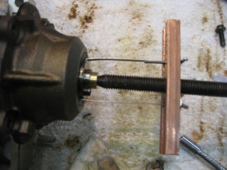
Compression test each cylinder.
Connect battery using jump leads between solenoid main battery connection and a ground (negative).
Then using a smaller lead, connect battery positive to the lucar connector on the solenoid. This powers the
starter and turns the engine over. The solenoid needs to be in the circuit since it pre-engages the starter
dog with the flywheel before connecting the battery to the starter motor. Sad to say it took me a while to
realise this as I am more familiar with the older technologies!
Cylinders 1 to 4 gave: 145, 148, 146 and 150psi.
These values were good enough for me to skip the wet test.
A leakdown test at 100psi showed >95% on all cylinders. All good news. Note the breaker bar on the crankshaft
pulley bolt, this stops the engine rotating if not at TDC when air pressure is applied.
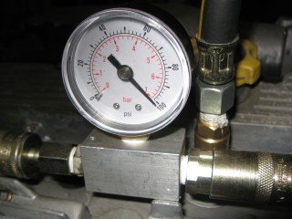
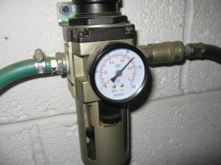
Test the coolant system as before by pressurising the header tank after sealing off all the coolant exit
points. I used my brake bleeding kit with air from the spare tyre at about 15psi.
(Observation: a 'D' cell is just the right size to seal off the larger pipes!)
Actually I ended up connecting two exit points together with that hose.
Nothing appears to be getting to the cylinders. The dipstick pipe was the only place where any
significant air was escaping.
I also tested the oil cooler separately but that showed no signs of leaking.
Press on with separating the engine and the manual lists the following operations:
Remove 2 bolts securing exhaust camshaft rear oil seal cover plate and remove cover plate.
Position lifting brackets 18G-1572/1 and 18G-1572/ 2 to cylinder head and secure with bolts.
Position adjustable lifting equipment, 18G-1598 to lifting brackets.
Connect hoist to 18G-1598,raise hoist to take weight of engine and gearbox.
Remove bolt securing rear engine steady to bracket on sump.
Remove nut and bolt securing gearbox mounting to LH buttress.
Remove 4 bolts securing LH buttress to subframe and remove buttress.
Remove nut securing RH engine mounting bracket to hydramount.
Remove bolt securing RH engine steady to engine mounting bracket.
Loosen nut and bolt securing engine steady to RH buttress, pivot engine steady from mounting bracket.
Remove bolt, loosen remaining bolt and move engine mounting restraining loop aside.
With assistance, raise and remove engine and gearbox from subframe.
Lower engine and gearbox assembly, disconnect hoist from 18G-1598.
The camshaft oil seal cover plate probably refers to the non-VVC head and I have no desire
to remove the cam sprockets at this stage. I don't have any lifting brackets anyway but I
do have plenty of rope. To give myself room to put a rope around the gearbox end of the engine
(I'm trying to keep the gearbox available for removal) I'll take off the plenum which is easy.
Removing the 4 bolts securing LH buttress to subframe caused me some grief. I managed the two bolts
at the front of the buttress but the rearward two were stubborn. I did not want to shear the bolts
and my cheap/cheerful impact wrench would not touch them. So, I actually went and bought a Sealey
GSA6006 which removed those bolts relatively easily.
So I can now get back on plan and remove the engine/gearbox from the subframe.
Again I have made life difficult by having the gearbox and the now open end of the subframe at the
wrong end of the crane. Anyway I got the subframe clear and rested the engine on wooden blocks on
the floor.
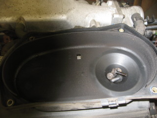
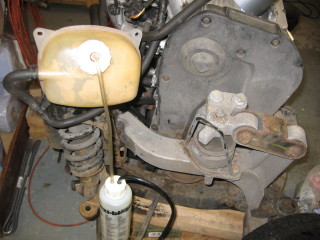
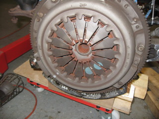
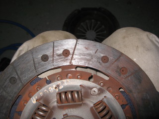
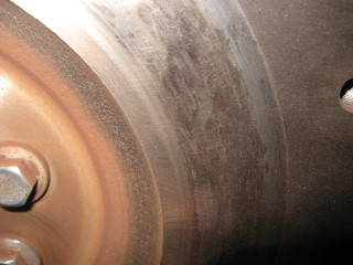
Now to have a look at the clutch. Just about worn out - add that to the shopping list.
There is some slight wear visible on the flywheel but no serious grooving. I'm going to live
with that.
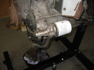
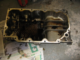
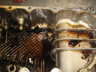
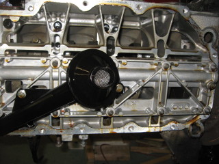
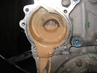
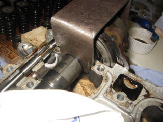
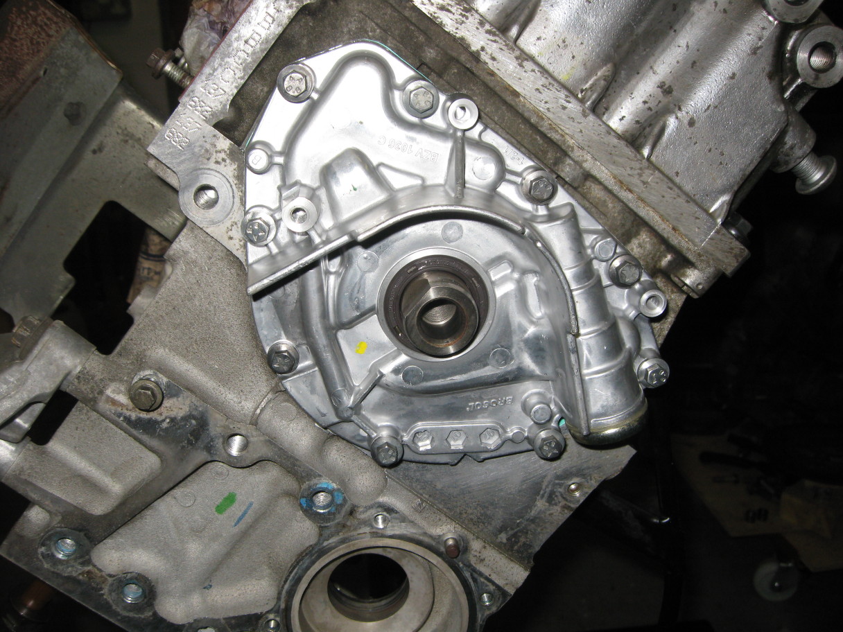
Now around the side to where the oil filter and oil cooler pipes are attached. Remove that.
Next up is the sump which came off easily once all the screws were out. Still a litre or so of
fluid in there so drained that off. The crankshaft area looks clean, the oil pickup pipe and strainer
are clear of any obstructions. The original oil rail is evident so that might get an upgrade.
Lumps of jellied sludge were disposed of and the inside of the sump roughly cleaned before popping it
back on the engine to keep the dust out.
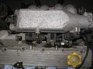
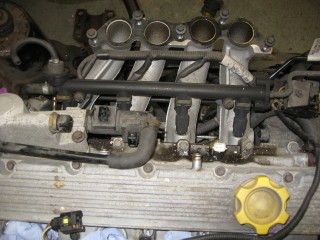
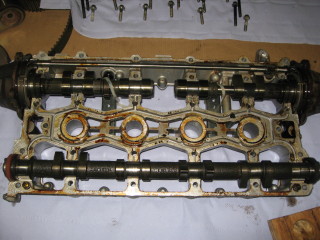
Now for the cylinder head. First the cam cover comes off - easy, but what horrors lie beneath?
A cam cover gasket is a thin metal sheet coated with ... well, I don't know what it is but it didn't
withstand the rigours I subjected it to!
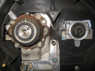
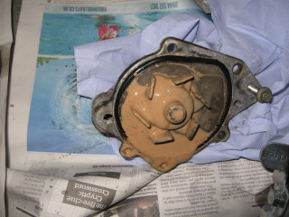
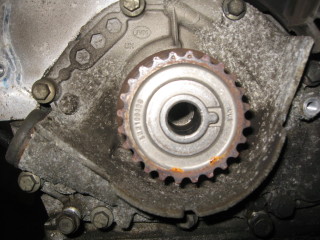
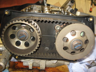
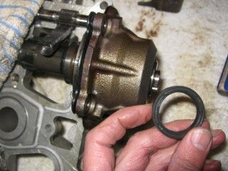
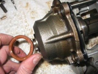
The cam belt at the front of the engine comes off next. Just release the tensioner (take it off unless
the belt is to be re-used) then ease the belt forward. Compare it with the new one to ensure it is the
correct width and has the right number of teeth.
Now I can remove the cam sprockets. I have a special tool which is quite effective here. It kind of fits
in the spokes while you unscrew the 17mm bolts. This exposes part of the VVC mechanism which is bolted to
both the cam rail and the cylinder head. So for now I will remove the cylinder head complete with the
camshafts. But, I'll take the water pump off first. More emulsion to mop up.
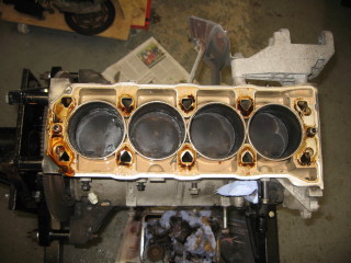
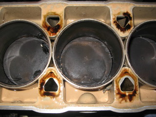
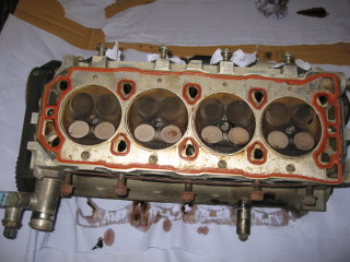
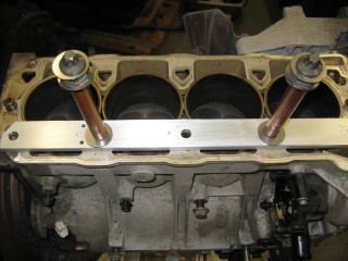
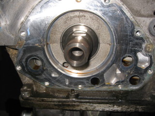
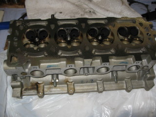
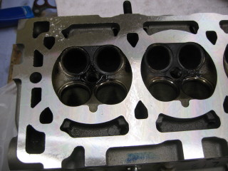
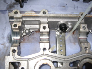
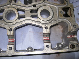
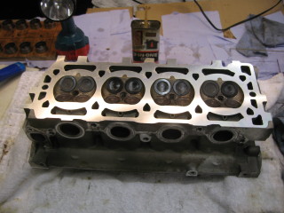
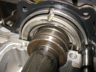
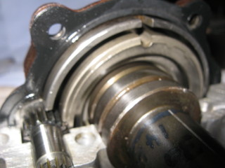
Now for the head. Ten stretch bolts later and a bit of jiggling and up it comes. Managed to get it to the
bench without dropping it. Examine the face of the block but cannot see any obvious signs of a path
between the water and oil galleries. Make a clamping arrangement to keep the liners in place in case I
need to rotate the crankshaft. Check the head and again no signs of how the oil could be getting into
the coolant. The head gasket is the single layer metal type with a 'rubber' bead around the oil and water
passages. Promisingly, I cannot find any indentations in the head which might indicate a softening of
the head alloy. This will, hopefully, be confirmed when I take the head to be leak tested.
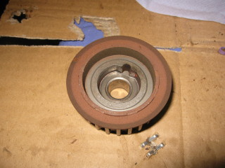
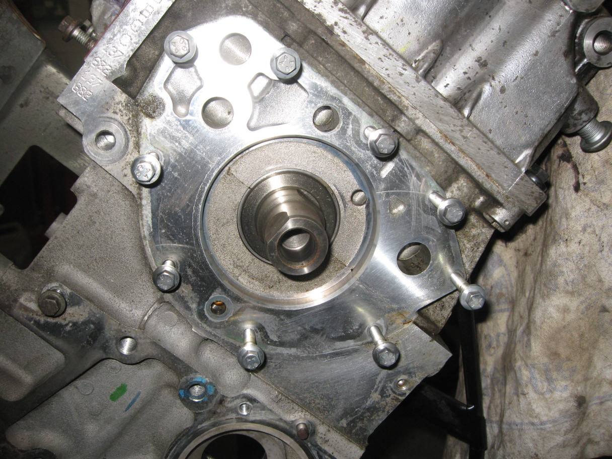
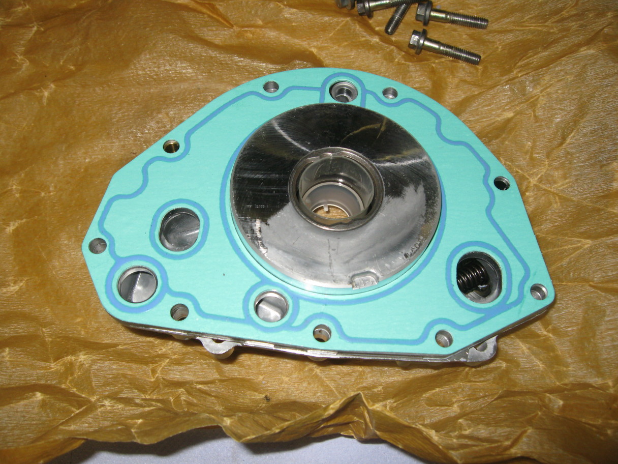
Pop the oil pump off - the cambelt drive wheel on the end of the crankshaft just pulls off. Eight screws
later and the oil pump can be pulled away from the block.
Now I can turn the engine upside down and let it drain while I get on with other stuff.
Need to get the head pressure tested and to do that the camshaft ladder, tappets, valves etc. need
to come off. This is definitely unknown territory for me - the VVC mechanism is not something to be
interfered with lightly. Even the 'K' Series Engine Overhaul Manual has the following dire warning:
"CAUTION: During the following operations, it is essential to ensure that the front and rear inlet
camshafts are retained in their respective assemblies. If camshafts are removed from their VVC
assemblies, then the complete assembly must be replaced; it is not permissible to refit camshafts to
VVC assemblies".
So, following the manual again, remove the camshaft carrier from the cylinder head:

Using a special tool that fits in the holes in the gear, rotate inlet camshaft rear timing gear until
timing marks on both rear gears face outwards. (With timing marks in this position, the lobes
of numbers 3, 4, 5 and 6 cams on the inlet camshafts should be facing upwards.)
Suitably identify each rear camshaft gear to its respective camshaft.
Using the special tool, this time to prevent the rear gear from turning, remove the bolt and washer
holding the rear gear in place.
Repeat for exhaust camshaft rear timing gear.
Remove both timing gears from their camshafts and discard the timing belt.
Remove four bolts securing camshaft rear timing belt backplate.
Remove rear timing belt backplate.
Remove oil temperature transmitter, from hydraulic control unit, remove and discard sealing washer.
Remove 3 bolts securing hydraulic control unit to camshaft carrier.
Withdraw hydraulic control unit, remove seal plate.
Remove and discard 2 labyrinth seals and rack seal from seal plate.
Fit camshaft gear bolt to front VVC mechanism.
Screw tool 18G 1299A and 18G 1299A-1 into oil seal.
Remove VVC housing oil seal by tightening centre bolt of tool, discard oil seal.
Remove camshaft gear bolt.
Repeat above procedures for rear VVC housing oil seal.
Remove and discard 2 bolts securing each VVC housing to cylinder head.
Slacken 2 bolts securing each VVC housing to camshaft carrier by 1 turn. (Do not exceed 1 turn).
Using the specified sequence, progressively slacken and noting the position of 4 longest bolts,
remove 32 bolts securing camshaft carrier to cylinder head.
Ensuring that front and rear inlet camshafts are retained in camshaft carrier and VVC assemblies,
carefully release camshaft carrier from cylinder head.
Lift camshaft carrier together with front and rear inlet camshafts off cylinder head. (CAUTION:
Ensure that exhaust camshaft is retained in cylinder head as camshaft carrier is removed).
Ensuring that front and rear inlet camshafts are retained in camshaft carrier, invert carrier.
Slacken but do not remove 2 bolts securing each VVC housing to camshaft carrier.
NOTE: Bolts should only be slackened sufficiently to enable timing plates 18G 1770/1 and
18G 1770/2 to be fitted.
Fit timing plates 18G 1770/1 to front and 18G 1770/2 to rear VVC assemblies.
Assemble clamps 18G 1770 to front and rear inlet camshafts and VVC assemblies, fit camshaft gear
bolts and washers to retain clamps.
Suitably identify each VVC assembly to its fitted position. Do not attempt to interchange front
and rear assemblies.
Remove and discard 2 bolts securing each VVC housing to camshaft carrier.
Remove front and rear camshafts together with VVC assemblies.
CAUTION: Do not remove clamps 18G 1770.
Remove control shaft from camshaft carrier.
Remove and discard exhaust camshaft oil seals.
For now I have simply held the inlet camshafts in place with metal bridges and tie wraps.
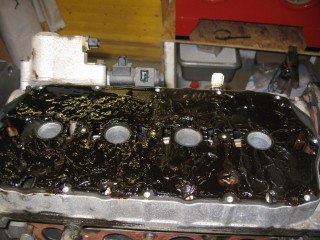
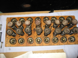
Using a stick magnet, remove 16 tappets from cylinder head. Retain tappets in their fitted order
and invert to prevent oil loss.

Support cylinder head clear of valves; use hollow drift and tap each spring cap to free collets.
Position cylinder head on its exhaust manifold face.
NOTE: K16 engine: Remove inlet valves with cylinder head in this position.
Using tool 18G 1519 and adapter 18G 1519/1, compress valve spring.
Remove 2 collets from valve stem using a magnet.
Remove tool 18G 1519.
Remove spring cap and valve spring.
Remove valve.
Using 18G 1577, remove and discard valve stem seal.
Repeat above operations to remove remaining inlet valves.
Position cylinder head on its inlet manifold face.
Repeat above operations to remove exhaust valves and valve stem seals.
CAUTION: Retain valves and springs in fitted order.
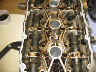
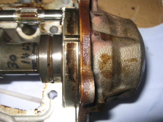
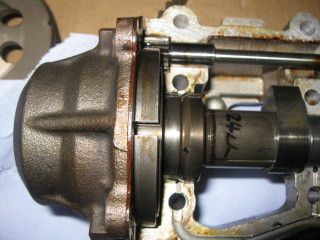
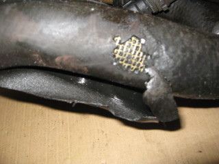
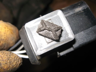
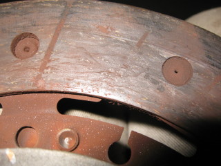
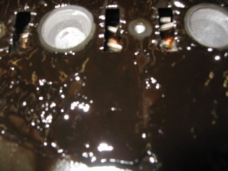
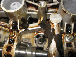
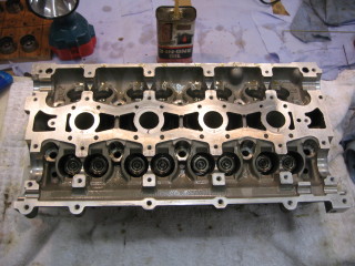
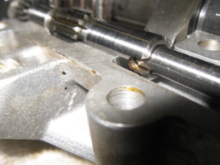
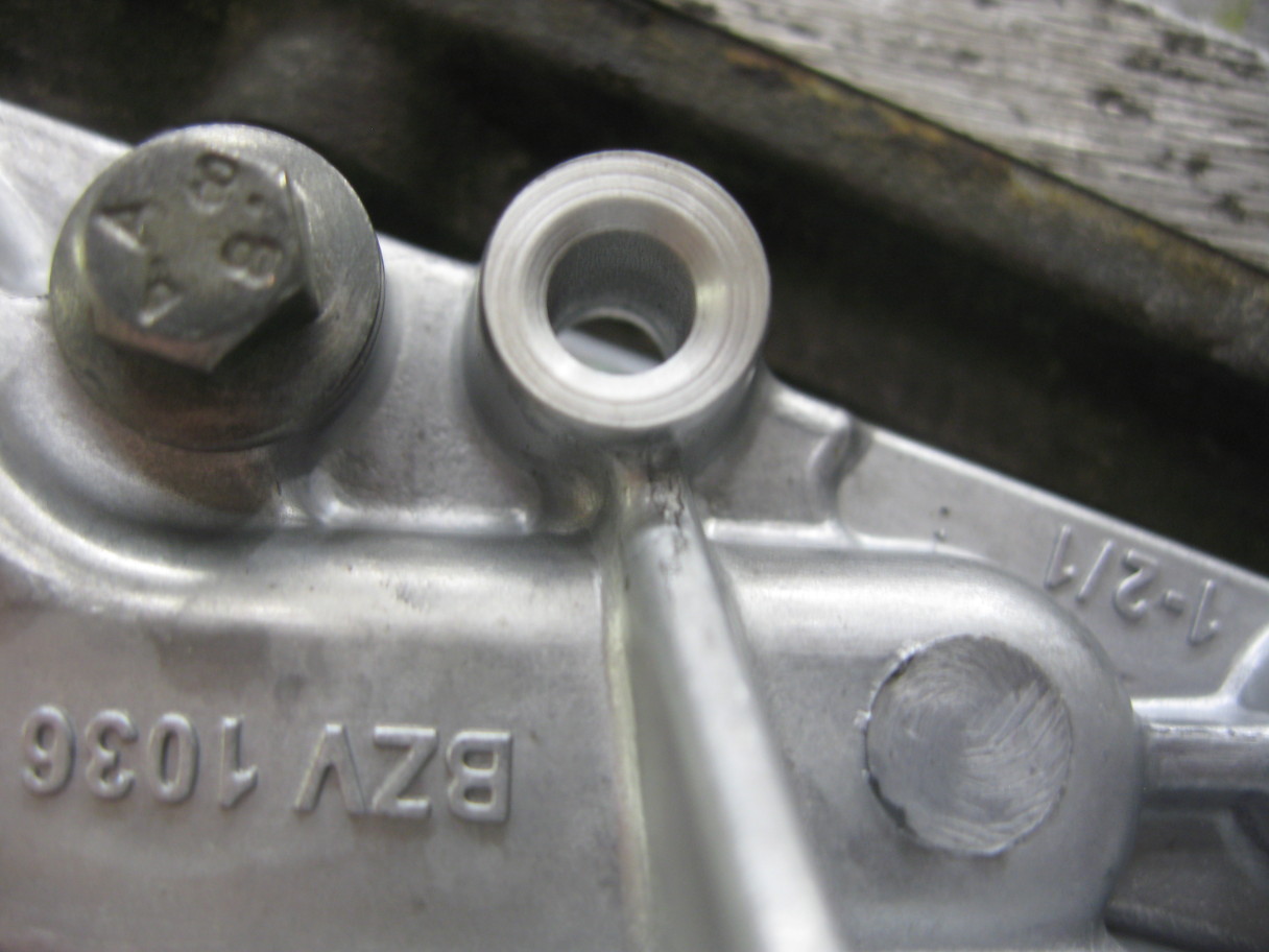
The close-up below shows a blocked oil gallery. I need to get the camshaft out to better assess
the damage.
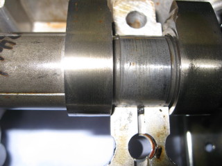
With the head in this state I can take it to be pressure tested.
Cylinder head has now been pressure tested and lightly skimmed.
Now to figure out a way to lift out the camshafts so that I can clean out the oil galleries.
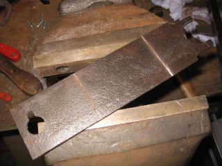
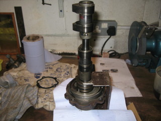
I have decided to make a pair of clamps styled on the 18G1770 which did not prove too difficult,
although if I did not have the resources then sticky-backed plastic and pipe cleaners would have
been used. I dare say that more than enough toilet roll tubes would also have been available!
The locking plates I replaced with some squashed brake pipe which stopped the internal mechanism
rotating inside the housing. With these in place I lifted the two VVC mechanisms and the sync
shaft out of the ladder.

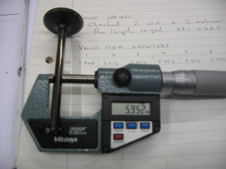
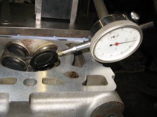
The bearing faces look ok and the clearances were checked with plastigauge. Tappet diameters were
also measured to be ok. The bad news was the valve stem to guide clearance which exceeded the
service limit but putting new valves and guides in was financially not possible. At least I am
aware of the problem and if I start to see oil burning I can decide what to do then. Hopefully
that will be a good few miles down the road.
Time to reassemble the head with new valve stem oil seals. Straightforward enough, just push the
seals down onto the top of the valve guides taking care not to scratch the bores where the tappets
slide. The same seals are used for both inlet and exhaust. Compress the valve spring and place
the collets on the valve stems using tweezers and oil as glue. Check that both collets are in
place when the spring compressor is removed. Don't put the tappets in just yet - wait until the
VVC mechanism has been checked.
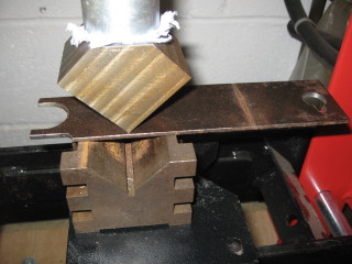
Putting the inlet camshafts back in starts with replacing the VVC mechanism gaskets. I gripped the
VVC clamp in a vice and eased the camshaft out sufficiently to get the old gasket out and put the
new one in.
Now put the cross shaft in place with the notch aligned with the mating face of the cam rail.
Then, ensuring that the timing notches in the mechs are still aligned, slide one of the camshafts
into the top rail, meshing the last gear tooth on the mech with the cross shaft and rotate the mech
down into its bearing keeping the gears meshed. The notch in the cross shaft must still be aligned
with the surface of the cam rail. Pop a couple of screws in to fasten the mech to the rail. A similar
operation gets the second camshaft into position and should be a mirror image of the first one. The
gears on the mechs should be at the end of their travel. Once you've done this a few times it gets easy.
Tie wraps hold the camshafts themselves in their journals and the clamps can be slipped off.
Put this assembly onto the bottom rail (no exhaust camshaft yet) and here I used the long screws and
tightened them up to make sure that the cross shaft was free to slide from side to side.
The VVC hydraulic control unit (HCU) was pulled apart (except for the valves), cleaned and fitted
with new gaskets. The procedure now is to push the rack up into the housing as far as it will go
and then slide the rack into the guide and engage it with the cross shaft. Put the three screws in
and nip them up. At this point, the second timing notch in the VVC mech should be visible through
the sighting hole in the rail. Now, with the temperature sensor removed, apply low pressure air
(I had 15psi) to the hole vacated by the sensor and check that the rack extends to the end stop.
No timing notches should be visible. If the rack jams it is usually the housing not in quite the
right position. Unfortunately there is no easy way to get the rack back up into the housing without
taking the HCU off. Having convinced myself everything was capable of working it was time to get
the glue out.
Pull the top and bottom halves of the cam rail apart and make sure everything is nice and clean.
I used carb cleaner to help clean off the sealant. Then the tappets were cleaned, oiled and put into
place as well as the exhaust cam shaft. I used IPA to clean the two mating surfaces ready for glueing.
The kit you get from Rover has a small plastic bottle half full of sealant, a scraper/spreader and a
brush. Here I tried to be clever and transferred some sealant to a small, empty syringe (no needle!).
I also have a small rubber roller. So I laid down the sealant as per the manual and spread it over the
surface with my little roller. I wiped away sealant which was encroaching on the journals and got the
two halves screwed together. Dinner time - cover everything up and off to get fed.
The next day tried to get the VVC HCU on but the rack refused to engage with the cross shaft. The
shaft would not turn easily, must have got some sealant in the bearing. After some working of the
shaft it became a bit easier and I got the rack engaged but would not reliably extend during the
compressed air test.
Split the two halves again, removed the sealant and cleaned the two faces. Applied some more sealant
still using the syringe but this time much more sparingly. Rolled it out and put it all back
together again. This time the cross shaft was easier to rotate and the rack engaged and extended
at 20psi.
Thought I would try a better test by applying compressed air to the oil gallery on the underside of
the cylinder head and energise the HCU coils so that the HCU piston would be pushed back into the
housing.
At this point I found that one of the coils was short circuit. Don't know how long it had been in
that state - hope the ECU is OK. I have seen articles on repairing these faults but I ordered a new
replacement for simplicity as these coils are completely potted.
Anyway, the remaining coil can be used to operate either valve but the air leaking around the journals
and tappets was too much and not enough pressure was available to operate the piston.
Made a simple puller and replaced all the four camshaft oil seals.
Fitted the back of the rear timing belt cover.
Fitted rear timing gears and timing belt to cylinder head.
Used carburettor cleaner to degrease the water galleries around the cylinder liners. Used nearly a full
500ml aerosol but it looks quite clean now.
Sandblasted the alternator bracket and put it back on the block.
Sandblasted the gearbox engine mounting bracket and put some black Hammerite on it.
Fitted the new oil pump and gasket. Used the original bolts which I cleaned with a wire brush and then
applied a couple of drops of Loctite 242 to the ends. Found that the two bosses on the pump housing that
support the engine harness are not tapped. The holes are there so it’s not a big problem; good job the
engine is out of the car.
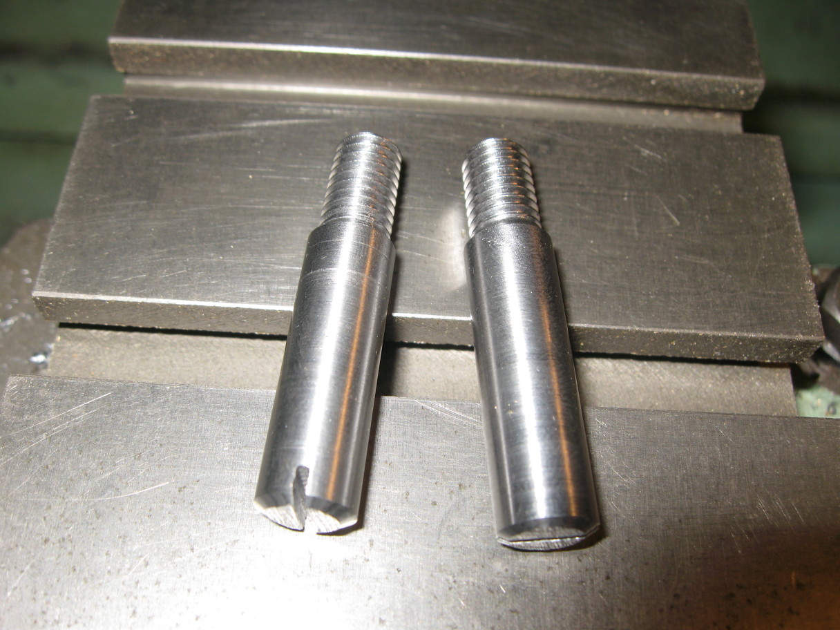
Put a 6mm tap into the holes in the oil pump ready to take the harness clips.
Fitted the metal coolant rail to the engine block using a new ‘O’-ring where the thermostat housing fits
into the aluminium casting.
Fitted the oil cooler and its bracket to the engine block.
Attached the hose between cooler and coolant rail.
Fitted the new water pump and ‘O’-ring.
Fitted the oil pickup to the new oil rail. Not sure about the two screws – they are slightly different
from each other and not as oily as I would have expected.
Got the sump ready to fit but found that I need two alignment pegs that screw into a couple of the bolt
holes and position the sump while it is being bolted into place.
Time to fire up the lathe and make those pegs.
And with further reflection I have decided not to fit the sump until the gearbox is fitted just to ensure
that the sump is not stressed when the gearbox to sump bolts are fitted.
Machine the two sump alignment pins. They hold the sump quite securely so very tempted to fit the sump
while the engine is mounted on the stand.

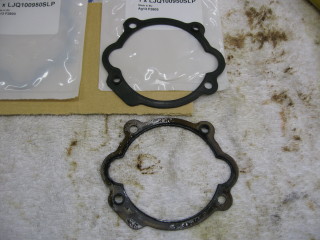
Took the coolant rail off to check the second ‘O’-ring where the rail meets the old thermostat housing.
It has become very spongy so I will replace that and the seal on the dummy thermostat. While it was off I
cleaned the inside of the metal pipes with a petrol soaked rag on a wire. While doing the smaller diameter
pipe a small plastic cylinder popped out! Cannot see it mentioned anywhere.

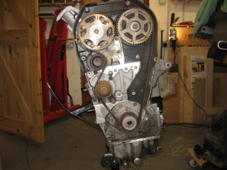
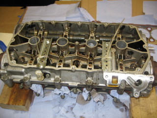
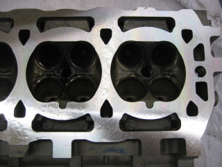
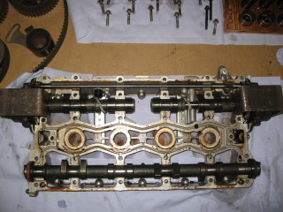
Mounted the cylinder head onto the block. Used the crane and bungies to lower the head onto the dowels
in order to avoid scratching the skimmed surface of the head.


Can you see what is wrong in the final picture above?
The cylinder head is the wrong way round!!
Torqued down the head (the right way round).


Timing gears, tensioner and belt fitted.
New ‘O’ ring fitted to dummy thermostat housing (both are now new) and refitted coolant rail.
Oil cooler refitted.
New ‘O’-ring fitted to oil pickup and tightened screws.
Checked screws holding new oil rail in position.
Cleaned the camshaft cover and put it in place with the gasket and all the screws but just finger tight.
Put the coils on the VVC HCU.
Cleaned out some coolant hoses and managed to get the quick release heater connectors apart, the ‘O’-rings
inside one half of the connectors had slightly adhered to the other half.
Cleaned the alloy part with two sensors that bolts to the head cleaned up ready for fitting.
Cleaned out some hoses. They all seem to be soft and swollen but otherwise intact. They will do until I am
happy that the cooling system is clean. No jiggle valve in this car.
Cleaned the gearbox housing.
Fitted sump using my alignment pins and the Threebond sealant (a plentiful supply).
Fitted cam cover with a new gasket and got all the screws torqued down.
Tightened the VVC HCU solenoids up. I had already fitted the new one using the old ‘O’-rings –
they just needed orienting.
Checked the coolant hose routing. There is small plastic moulding which came out of the coolant rail
feeding the oil cooler. This is a good fit in the 4-way junction and is possibly a deliberate restriction
to give better coolant flow through the heater matrix.
Started cleaning the old oil filter adaptor gasket off the block. This will need scraping off as it
seems to have bonded to the engine block.
Got the remains of the oil filter adaptor gasket off. Cleaned both faces and reassembled with a new
gasket. Loosely fitted the oil pipe support brackets and the oil cooler unions.
Fitted the coolant outlet with a new gasket and torqued the screws.
Loosely fitted the timing belt covers after giving them a bit of a clean.


Cleaned and painted subframe and mounts with Hammerite.


Torqued the engine steady bracket on the bottom of the sump.
Tightened the oil cooler unions and the clips holding the pipes to the sump.
Used some bolts screwed into the cylinder head to provide anchor points for ropes to lift the engine
off the stand and rest it on a dolly.
The flywheel is slightly scored but not enough to warrant a replacement.
Fitted the new clutch plate and cover using a home made alignment tool.


Fitted the two dowels which locate the gearbox. Put the new release bearing on the forks in the gearbox
and married the engine and gearbox without too much difficulty.
Torque the four gearbox to engine block bolts to 80Nm.
Fit the bell housing cover at the exhaust side. Two massive 14mm bolts!
Bead blast the front engine mount bracket then Loctite the four bolts and torque them to 40Nm.
Fit the front lower timing belt cover.
Crankshaft pulley fitted. Used air impact gun on max to tighten. Checked as best as I could by locking
the flywheel and setting my biggest torque wrench to its max of 110ft.lb (=150Nm). Should be 205Nm.
Starter motor fitted and bolts torqued.
Fitted the timing belt cover and torqued the screws.
Cleaned the engine wiring loom and tidied it up using self-amalgamating tape.
Engine loom screwed to oil pump and vaguely routed.
After several trial fittings of the engine-less subframe to the car I got the crane out and lifted the
engine and gearbox into position on the subframe and loosely fitted the right hand (alloy) buttress onto
the subframe.
Torqued sump to gearbox (2 bolts).
Torqued RH engine mount to engine bracket.
Torqued LH mounting brackets to gearbox.
Torqued the buttresses to the subframe.
Fitted the RH engine mount to buttress.
Fitted both the top and bottom restraining links.
Fitted the LH engine mount to the buttress.
Torqued all the engine mountings.
Fitted the alternator loosely.
Existing exhaust manifold fitted with new gasket.
New down pipe fitted with new gasket.
Upstream lambda sensor fitted.
New alternator belt fitted.
Inlet manifold and plenum cleaned and torqued with new gaskets.
Checked routing of engine harness. Engine harness fitted
New spark plugs and leads fitted. HT cover cleaned and fitted.
Engine and gearbox now fully assembled to subframe. Put this to one side while I do the brake pipes.


Used the drain pump from the old Hotpoint washing machine to make a machine to flush out the
radiator and heater systems of the MG.
Ran some hot soapy water through the radiator for about half an hour. No obvious cold spots
and good flow so will refit.
Ran some hot soapy water through the heater for about half an hour in each direction.
Flushed with a couple of gallons of water. All looks fine.


Made up the front to rear brake and clutch pipes. Also the engine compartment brake pipes. I had tried a couple
of commercial pipe bending tools but was not impressed; bend radii too big. So, I resorted to making my own.
I had also bought a pipe straightener from Viper Performance which worked very well.
When I lowered the engine/subframe I found that the clutch pipe protruded into the engine bay enough
to make it necessary to bend it out of the way. To prevent this happening in the future I deliberately made
the new one about 20cm short. A short extension pipe then gives me the correct length. (That's my story
and I'm sticking to it!).


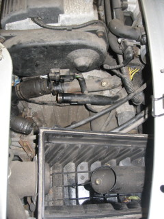
Cleaned around rear subframe front mounting points and applied Rustbuster FE123. Checked inside the offside
sill using the borescope. Looks OK.
Removed the fuel/air filter carrier, sand blasted it and applied FE123.
Silver Hammerite applied to areas with FE123 on them – subframe front mounting points, nearside and offside
mounting points for rear bumper.
Fitted the underbody clutch and brake pipes replacing the plastic clips where necessary. Not yet connected
under the bonnet.
Painted the fuel/air filter carrier with black Hammerite.
Fitted the engine compartment brake pipes and junction.


Tried to pump fluid along the clutch pipe but the pedal just fell to the floor and needed to be pulled back.
Tried ‘priming’ the master cylinder but that just filled up the reservoir. Finished up taking the master
cylinder off. Getting the clevis pin off was not easy and am not looking forward to refitting it. There
doesn’t seem to be much pressure at the outlet, perhaps the seals have hardened. Access to the innards
requires the removal of an internal circlip with really small holes. So bit the bullet and ordered a
repair kit, new flexible hose and a pair of small circlip pliers. That lot should be here next week.
Fitted the fuel/air filter carrier.


Sand blasted the clutch slave cylinder.
Cleaned the air filter box and input pipes.
My Eezibleed brake bleeding kit did not come with a lid suitable for the MG which has a bayonet style
fitting so set about making one.
Connected the radiator hoses to the underbody pipes.
Cleaned and undersealed the underbody pan. Bolted it back in place.
Lifted the engine and subframe back in place and loosely fitted the 10 mounting bolts. This went a lot
smoother than when I took the engine out.
Torqued the 10 mounting bolts and removed the supporting framework.
Fitted the hose clips to the radiator hoses at the front of the stainless pipes.
Trying to figure out cable routings and how the PRT assembly is located.


I think I have the PRT hose assembly sorted. Some concern about the heater connections, does it matter
which way the coolant flows? I need some jubilee clips for the radiator pipes to make it easier to remove.
The bayonet connections seem to be very sticky and difficult to separate.
Put new fuel filter into place but not connected yet.
Connected the battery positive cable to the starter solenoid. Found that I had routed it over the top of
the subframe, it needs to go underneath or it doesn’t quite reach. Also, the nut on the solenoid had corroded
and was threatening to unscrew the threaded portion which would mean a new starter motor. PlusGas was not
sufficient. Did not want to remove the motor so tried warming up a socket and transfer heat that way.
That worked. Cleaned up and secured the cable.
Having problems with the ECU and the large multiway plug, it won’t lock into place.
The large ECU plug has a damaged locking mechanism. I probably did this when first trying to fit it. Managed
to bodge it so that it locked into place but I will get some large tie-wraps for extra security. The rest of
the wiring went without a problem.
Got the new silencer down from the loft (it’s really heavy!). Getting the catalytic convertor off the old system
is not going to be easy so temporarily fit the old units. Put the lambda sensor in.
Finished the coolant pipes including the header tank and its pipes.
Radiator installed.
Used about 10 litres of water to fill system. Could not open the bleed valve for the radiator so left that for
the moment.
Put 5 litres of oil in and connected a fully charged battery.
After just a few revolutions the engine started and idled nicely. Left it idling while I monitored for leaks.
Once up to temperature I revved it to 6000rpm to verify the VVC was operational. Switched off.
YAY!!


Gear selector cables routed and clipped into position. Fitted new gaiters. When I got them, they came as a pair.
The one that moves the gear selector in and out of the gearbox fitted correctly. The one that rotates the selector
needed to be twice as long. Salvaged a usable piece from the old gaiters and fitted that as well. Should afford some
protection, certainly better than what it was.
Clutch slave cylinder piston removed – that and the bore look good.
Removed the old flexible pipe and found that the unions are welded together with corrosion. Will make a new copper pipe.
Started the engine again. This time ran it until the radiator fan started; mostly idle (900rpm) but some periods at
2000 to 2500rpm. Checked the input and output temperatures of the catalytic convertor – about 300°C and 400°C
respectively which indicates that the cat is working. Could do with a coat of paint to hide the rust. Switched off.
Everything seemed ok until I noticed an oil leak coming from the near side of the engine. It looks as though an
exhaust cam seal is the problem. New seals were fitted during the rebuild but I might have damaged it in some way.
Need to get the cam sprockets off to access the seals and verify. There is a remote possibility that the oil leak
is due to the back end of the car being very high off the ground. So, I will fit the clutch slave and tie the hose
pipes together and lower the rear end before checking the oil leak again.
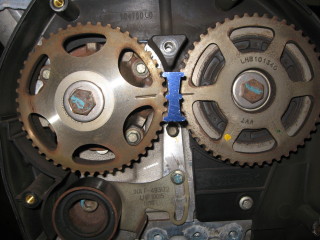
With the rear of the car lowered, I ran the engine again at about 3000rpm until hot – no leaks! Switched off and as it
cooled the leak started. Got the front cam belt cover off, aligned the sprockets and put the locking device in. Used
the impact hammer to get the sprockets off the rear of the engine. With the sprockets out of the way, the seals were
plainly visible. They were the black ones which should be fitted to the front of the camshafts!! Round to the front
and managed to get the inlet sprocket off after releasing the tension in the belt. Definitely red, so I had fitted
the seals the wrong way round during the rebuild.
(Expletives deleted)


While waiting for the new oil seals I managed to get the cat off the old exhaust system.
Removed as much rust and debris from it as I could, masked off the flanges and sensor hole and gave it a coat
of silver high temperature paint.