

This year (2017) I really need to do some restoration work on the Hornet. For all that the Hornet has been in the family since before I was born, I do not have a detailed history for it, I know that it was stripped down during the WW2 and stored in the house and an allotment shed. I know that it suffered a puncture and ended up upside down in a ditch and that all four of us escaped without injury. I, myself, have had three accidents which have damaged the near side front, the near side running board and the petrol tank. The mileage it has covered is unknown mainly because the odometer only goes up to 9999 miles. Finally, it has been off the road for the last 40 years.
So the basic idea is to get down to a bare chassis as quickly as I can so that it can be checked for integrity and alignment. Once that has been accomplished I can refurbish all the parts as it gets reassembled. This means removing the body/frame, engine/gearbox and both the axle assemblies. In order to do this I have to re-organise the garage as over the years the car has become buried.
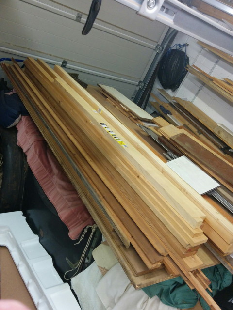
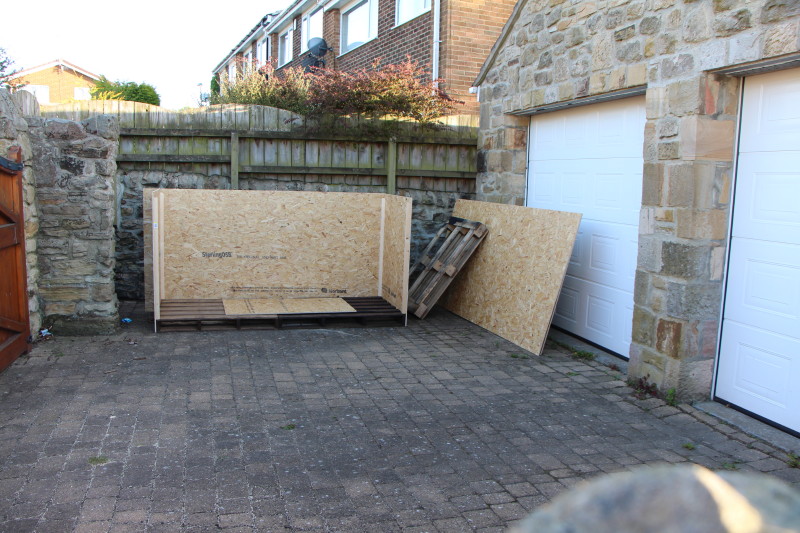
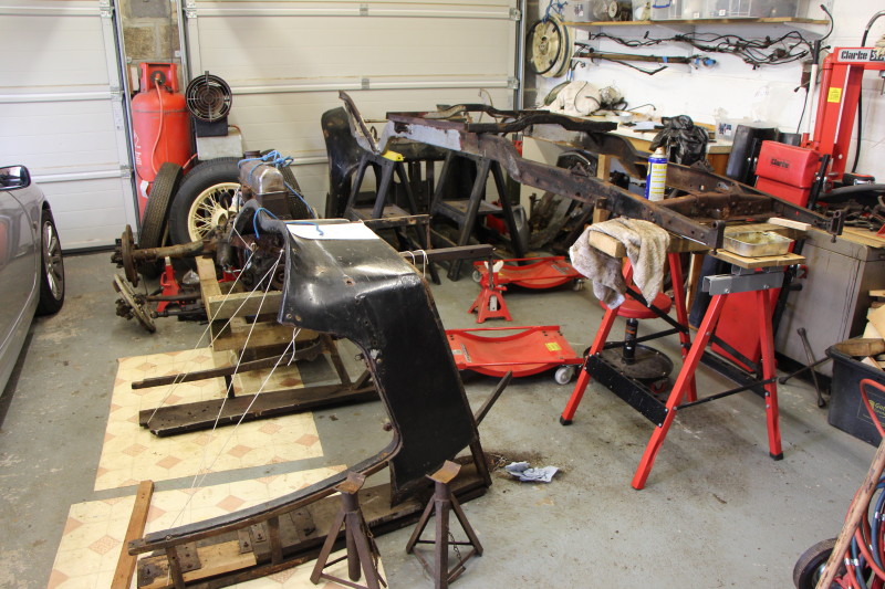
There is a Hornet in this picture!
Obviously my first job is to clear all the rubbish away. Some of the 'rubbish' comprises spare engines, gearboxes, diffs etc. and I will be making a storage box in front of the garage to hold the bulkier items.
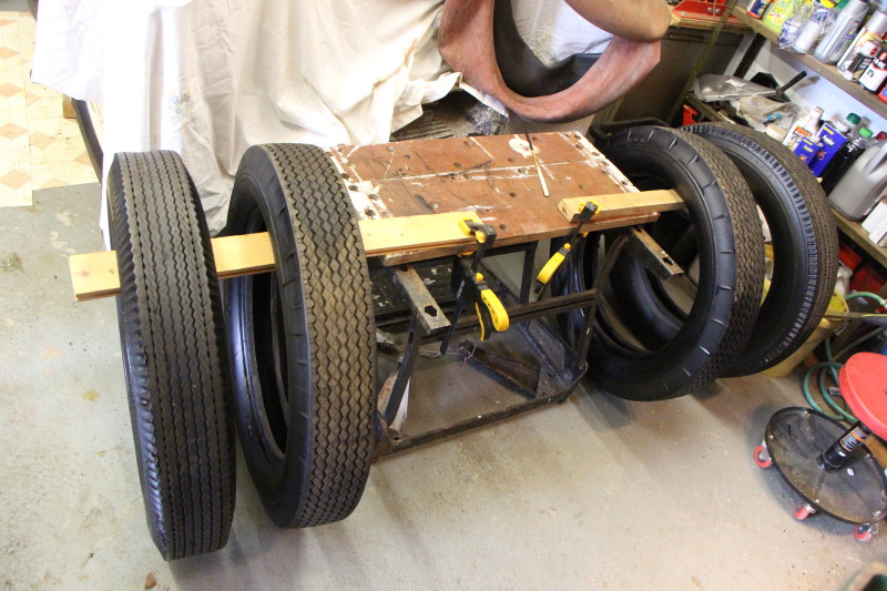
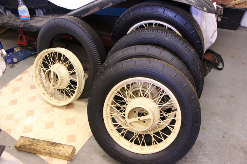
I then need to move the car out of the way while I install a bench along the far wall. The car is on axle stands at the moment and most of the tyres lose pressure quite quickly. So that I can roll the car in and out of the garage I need new inner tubes (the tyres are over 50 years old and will be replaced later). A set of 5 tubes, rim tapes and valve caps were duly bought in from Longstone Classic Tyres.
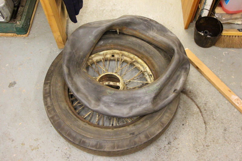
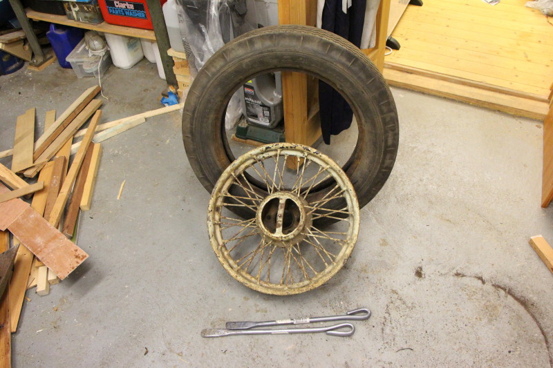
Wheel, tyre & tube separated!
That was a struggle:
Deflate the tyre by removing the valve insert.
Push the valve through the hole in the rim.
With the wheel face up on the floor, stand on the tyre wall to break the seal to the rim and
force the tyre bead into the well of the rim.
Turn the wheel over and repeat. The tyre will need supporting on blocks to prevent damage to the hub cap mounting stud.
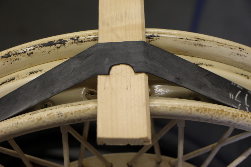
Insert a tyre lever under the bead of the tyre near to the valve - sounds easy!
Lever it over the edge of the rim.
Insert a second tyre lever a short distance from the first - again, sounds easy!
Lever a bit more of the bead over the rim.
Repeat this process as you work your way round the tyre.
With the tyre half off, pull out the inner tube. I found "builders" gloves got a better grip than my bare hands.
All that remains now is to lever the tyre off the rim completely.
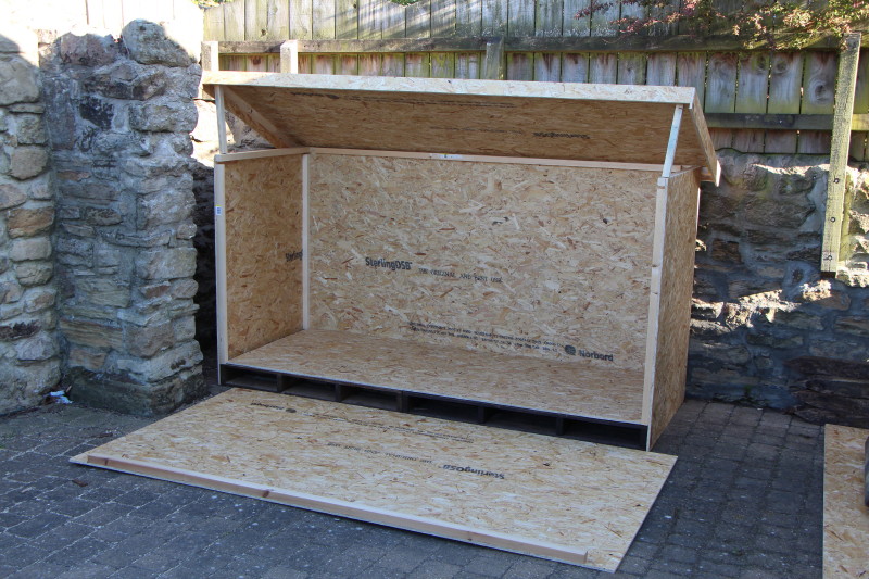
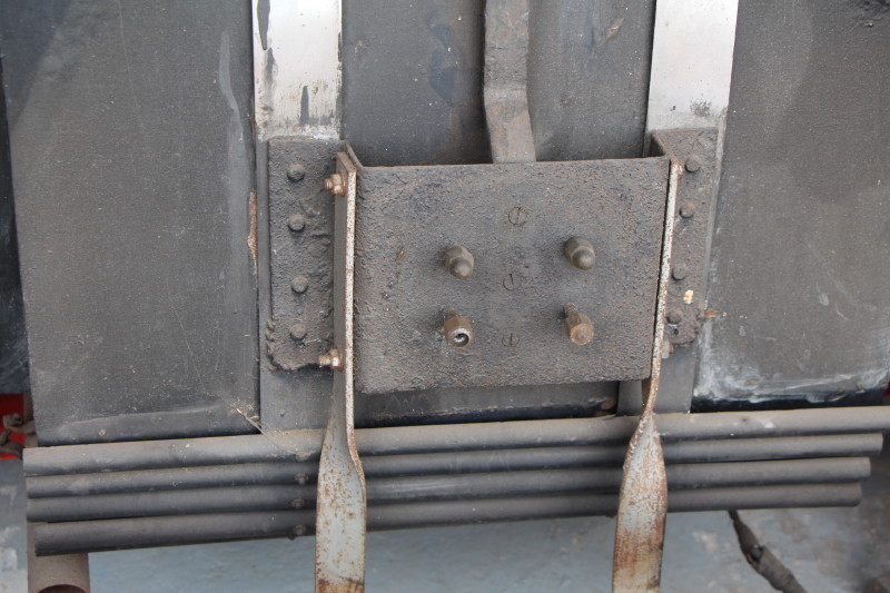
Had 5 sheets of 11mm OSB3 Stirling board delivered and started building my storage unit.
Very basic - two creosoted pallets bolted together keep everything off the ground. Stirling board back screwed to pallets and each side panel with the help of some 35mm square softwood. A floor was dropped in. Front panel left loose for now. Lid has timber stiffening and drips. This is also left loose for the time being. I will put in a shelf later.
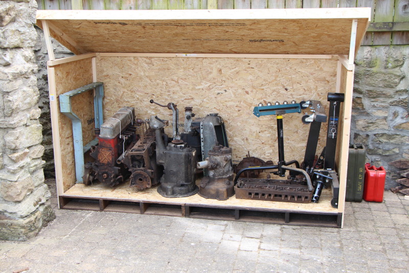
So, the contents of the box currently comprises:
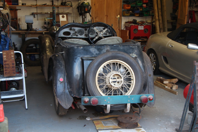
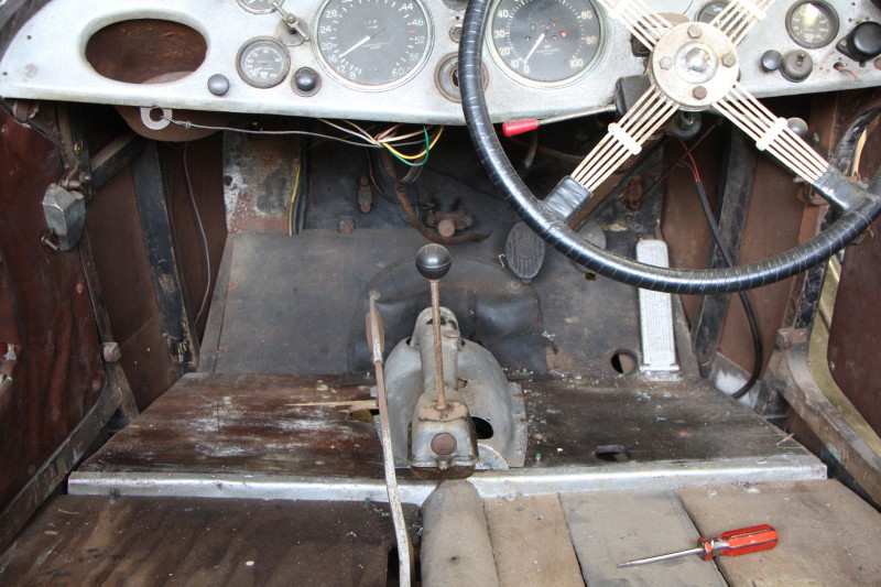
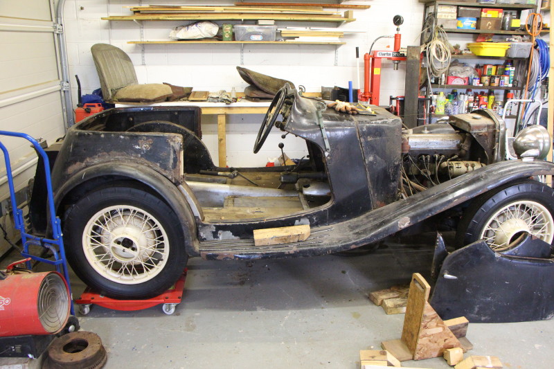
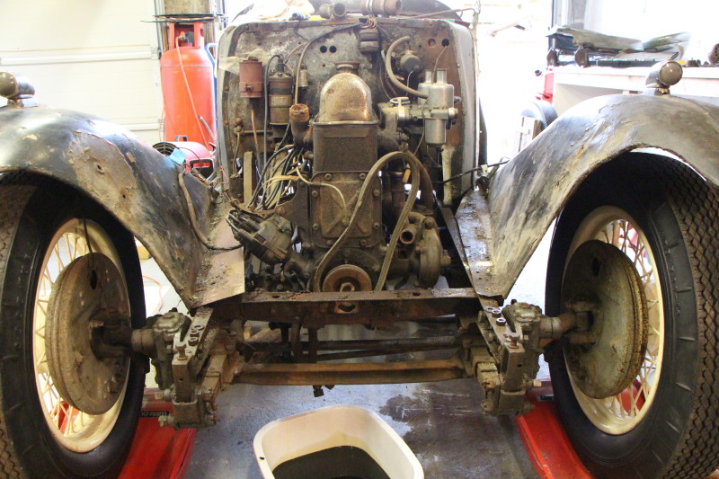
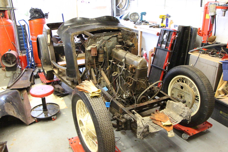
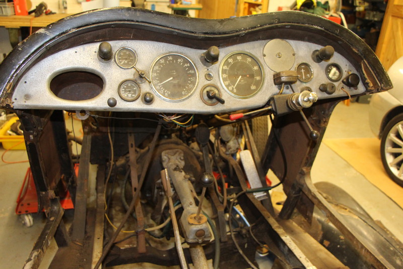
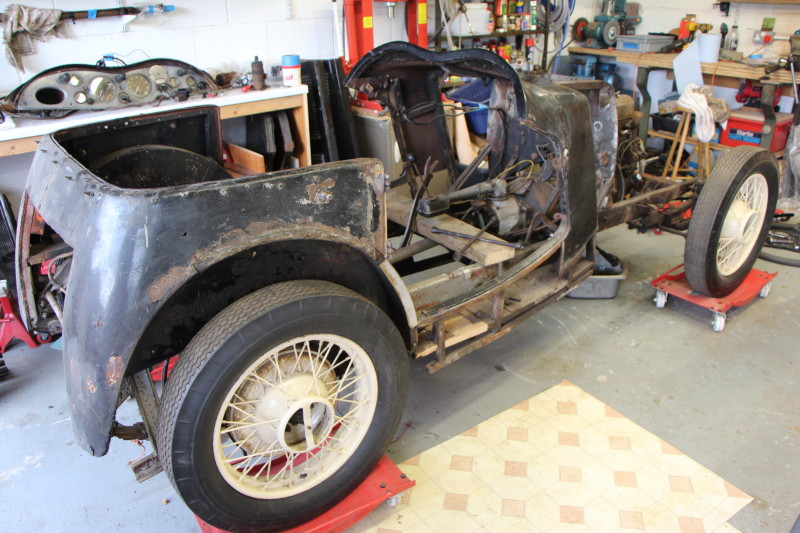
Having got those bits out of the way I cleared away the wood and other miscellaneous items covering the Hornet. Put the steering wheel back on. Good to see it in all its glory again but resisted the temptation to get in and daydream!
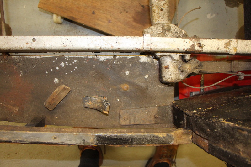
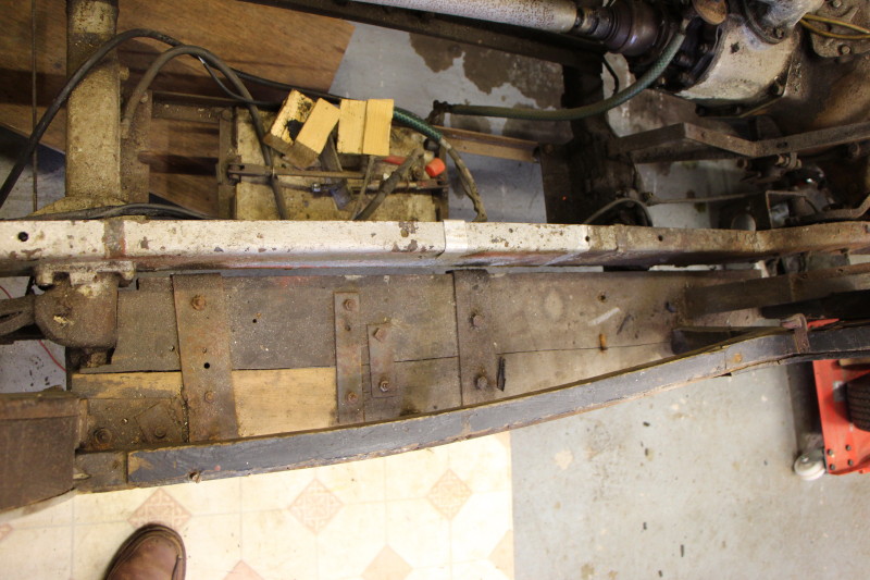
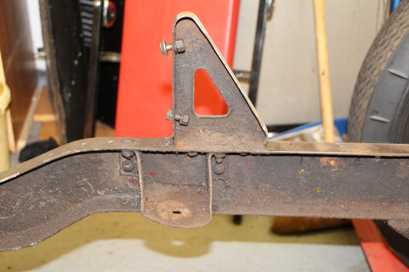
One of the first jobs will be to crawl underneath and see what condition the chassis is in.
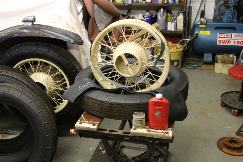
I now have a supply of talcum powder and tyrewall black paint so I can return to the wheels and tyres.
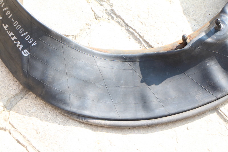
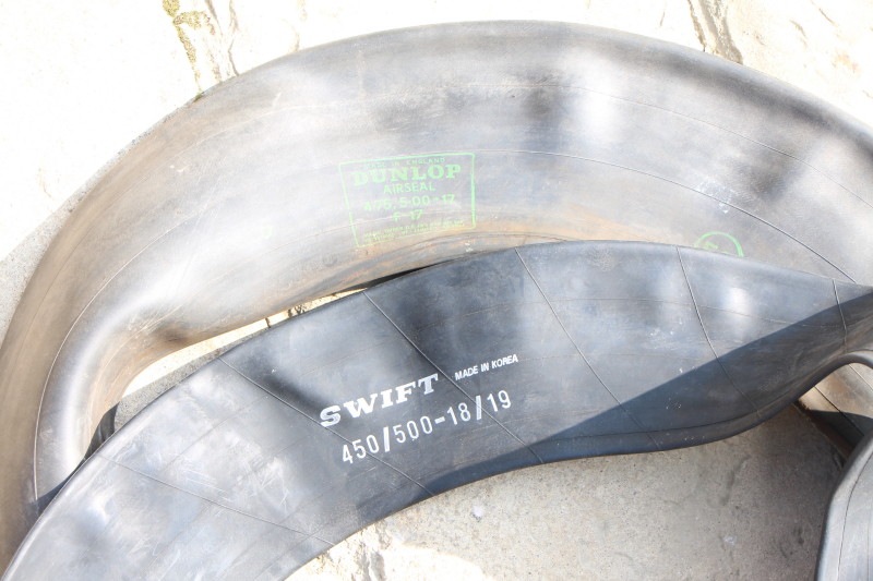
The new inner tube from Longstone is labelled 'Swift' and the old one is a Dunlop. They are noticeably different.
The Swift is smaller and thinner than the Dunlop.
The Swift weighs 783g against 1339g for the Dunlop.
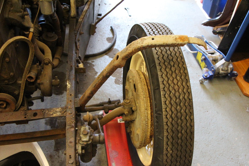
I have also been underneath and examined the chassis which does seem to be in reasonable condition; certainly not bad enough to warrant seeking out a replacement. So far so good.
The next step is to clean up the wheels and put new tubes in at least four of them and drop the car off its stands so that it can be rolled in and out of the garage while I do some rearranging.
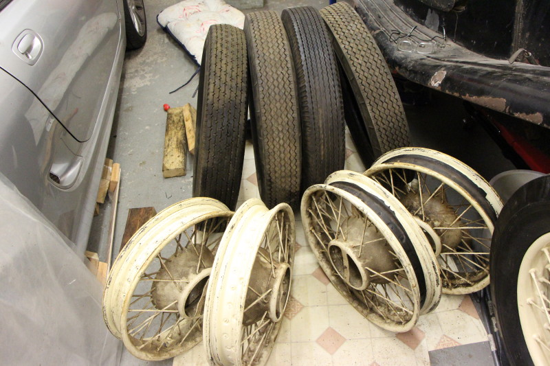
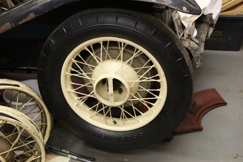
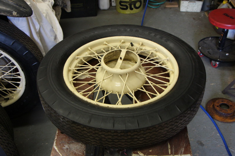
The following photos show the wheels at various stages.
Each tyre was scrubbed, dried and painted with the tyrewall black. Once the paint had dried (overnight) the inside of the tyre had any debris removed and given a dusting of talc. Each rim was cleaned using WD40 and rag. This is a most tedious process; each rim has 48 spokes so it took quite a long time. New rim tapes were fitted and given a small cut-out for the valve using a craft knife. Each tube was dusted with talc and inflated slightly to give it a bit of shape and reduce the probability of 'nipping'. the tube was inserted into the tyre and vaseline applied to both the inside and outside edges of the tyre wall; this makes life a lot easier when refitting the tyres. The tyre can then be levered on to the rim taking care that the inner tube does not get trapped. Having completed four wheels I am still unsure how best to get the valve through the hole in the rim but I managed. Massage the tyre to ensure it is in the correct position and inflate. I put in 35psi after realising that I had not the foggiest idea what the correct pressure should be.
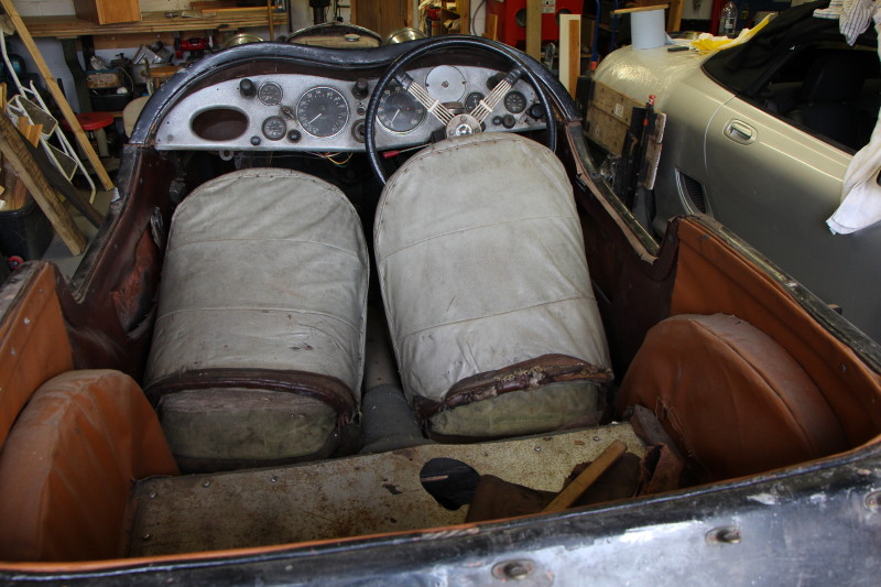
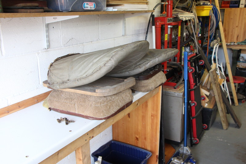
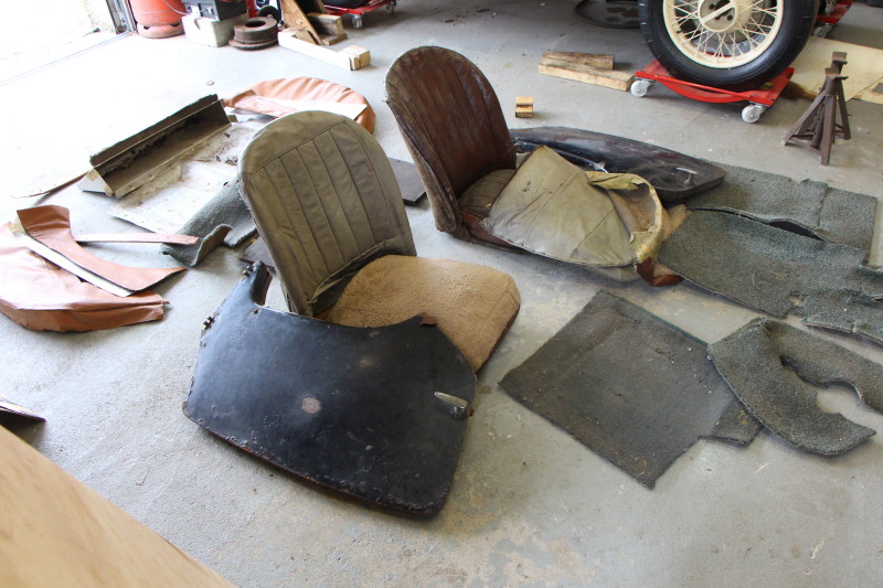
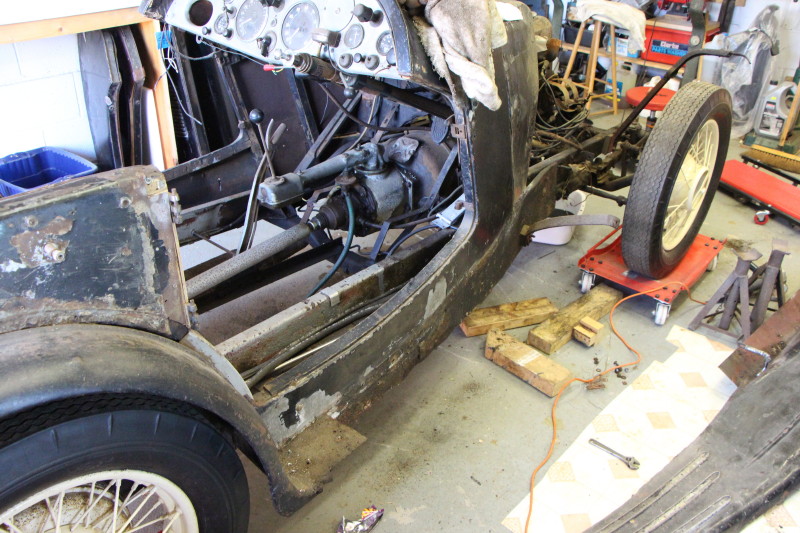
After rearranging the garage a bit I can now start taking the Hornet apart. The windscreen and rear seat/fob were removed a considerable time ago. My mum did a reasonable job of re-upholstering them but I will probably re-do all the seats etc. again so that they all match.
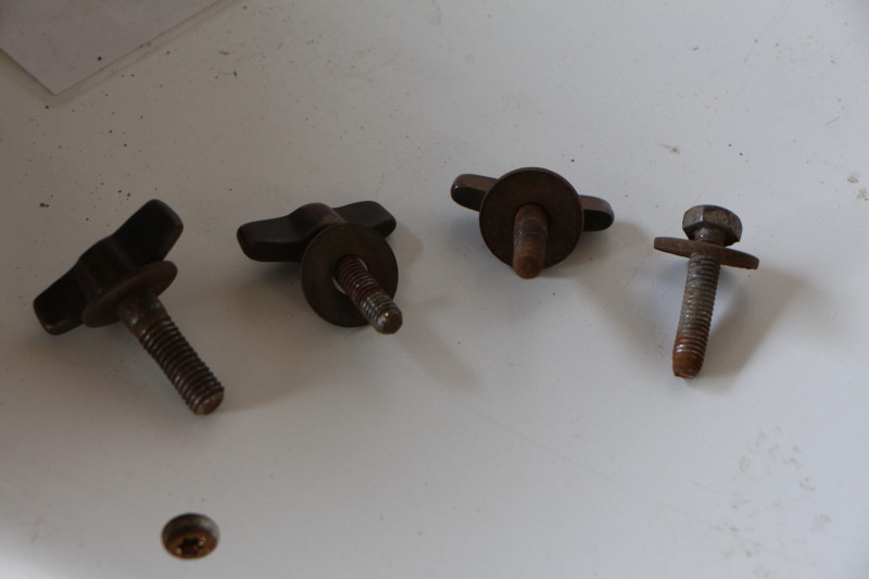
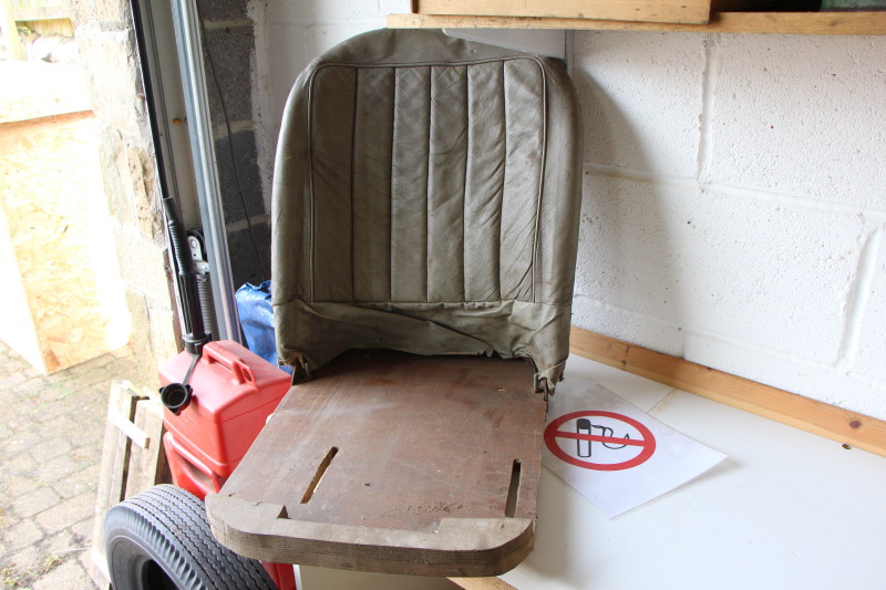
The front seats come out easily; just 3 wing bolts and an ordinary bolt hold them in position. The backs have been recovered in the past and the seats have had a complete makeover. The original seats had inflatable cushions but they are long gone replaced by some Dunlopillo I think it was called. Removing one of the seat back covers reveals what is probably the original dark brown leatherette.
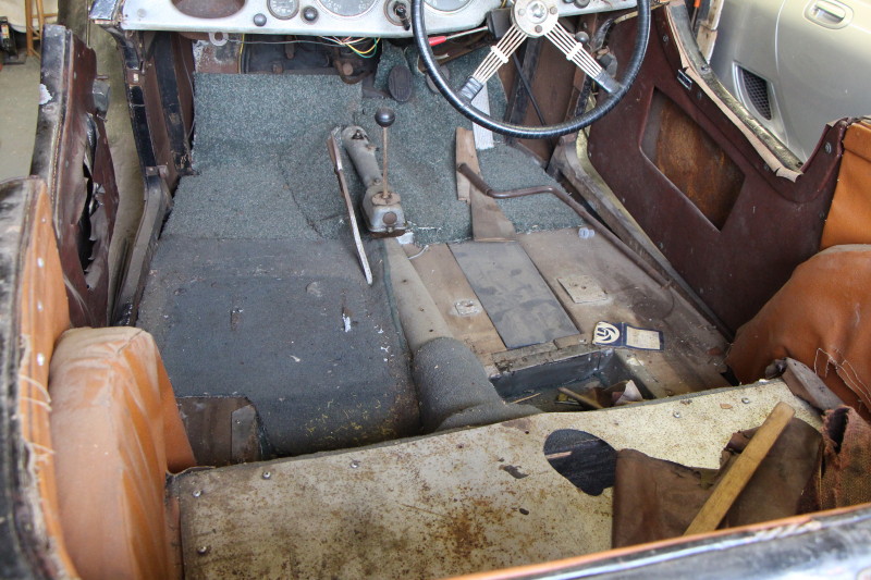
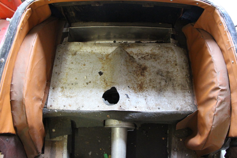
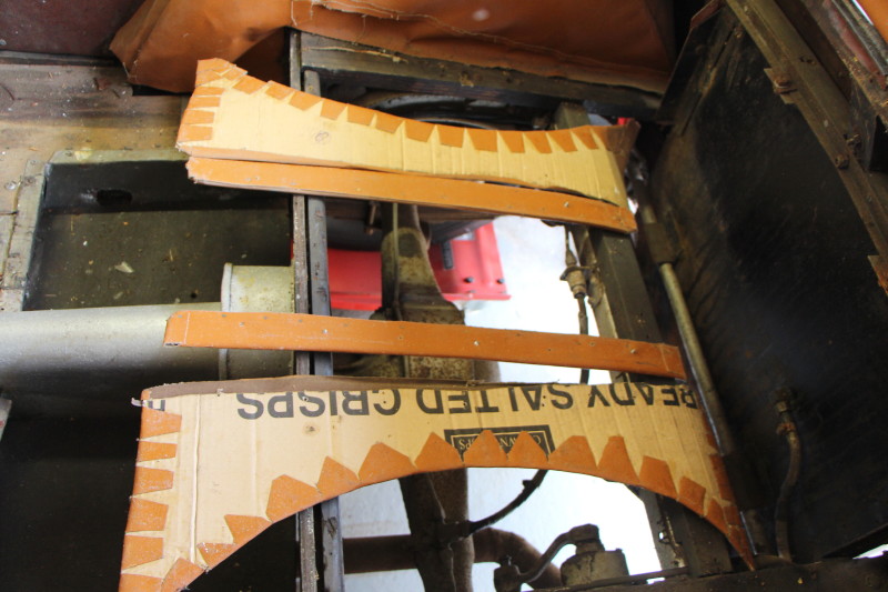
With the seats removed, the carpets came next along with the rear upholstery. Looks as though mum pressed an empty box of crisps into service to make the panels!
To make access easier, the doors were taken off by simply unscrewing the hinge pins.
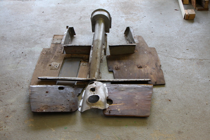
Then the floor and prop shaft tunnel were taken out.
All pretty straightforward so far.
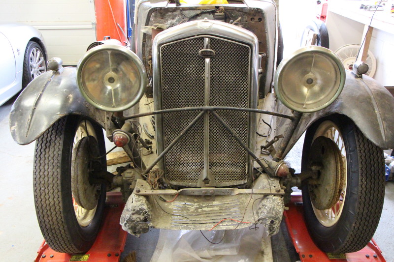
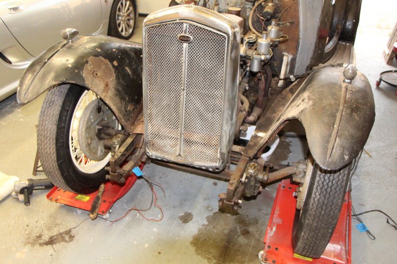
The next objective is to remove the headlamp assembly and the radiator.
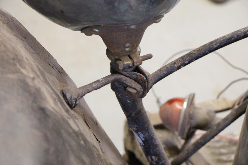
The headlamp support frame is held in place with special brackets at the top and bolted to the chassis at the bottom. These are the same bolts that hold the shock absorbers in position.
The headlamp's glasses and rims were removed to gain access to the wiring at the rear of the reflectors. The wires are held in place using spring loaded contacts rather than screws and were disconnected easily. The wires were then pulled down through the support tubes, labelled and put to one side. The headlamps were then reassembled.
The top brackets, although quite rusty, came off fairly easily.
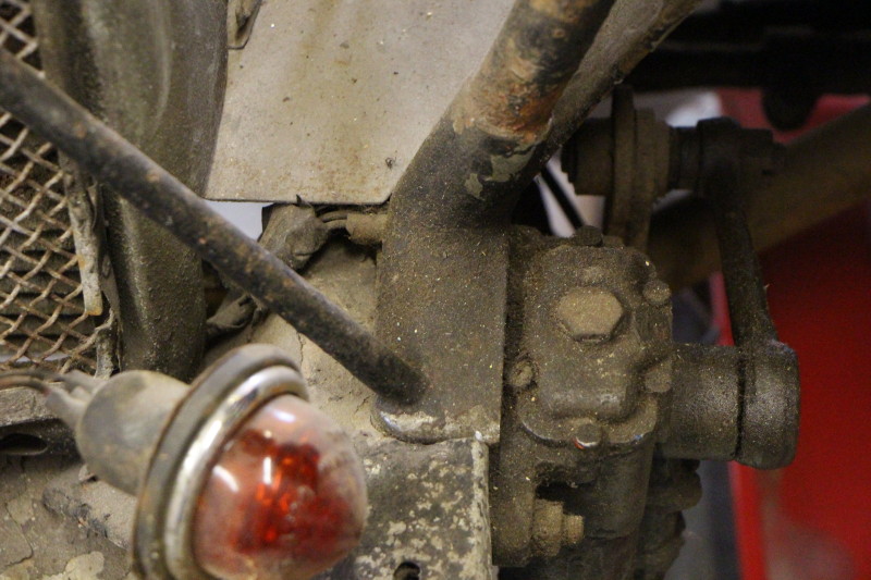
The bottom bolts were oily and were undone easily. The shock absorbers were bolted back on the chassis to keep track of the bolts.
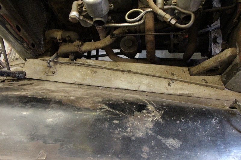
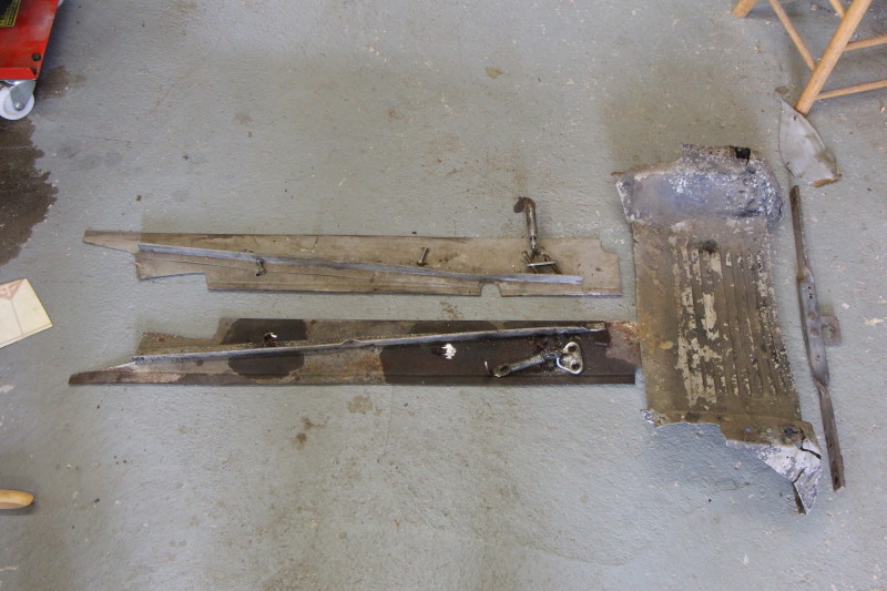
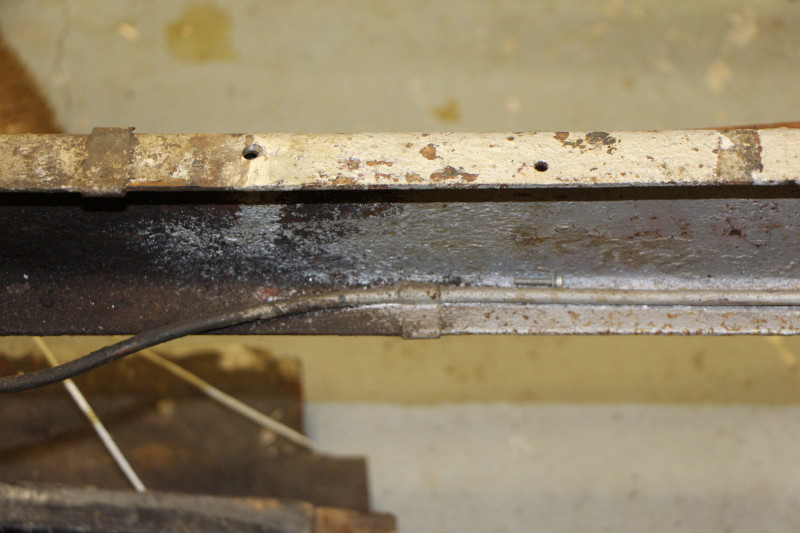
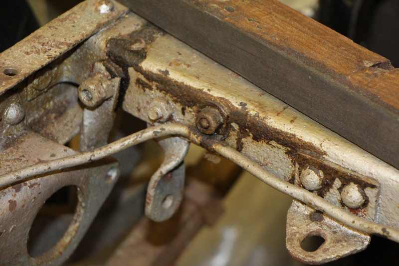
During this process I also removed both the near side and off side bonnet locating panels that run along the top of the chassis. Some of the bolts were badly rusted and I had to grind the heads off the bolts.
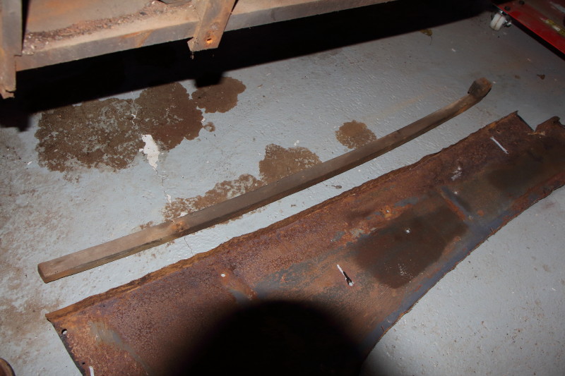
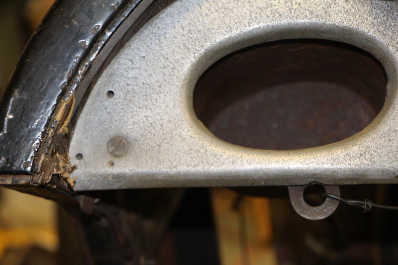
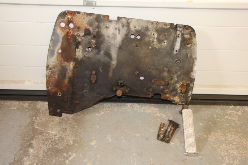
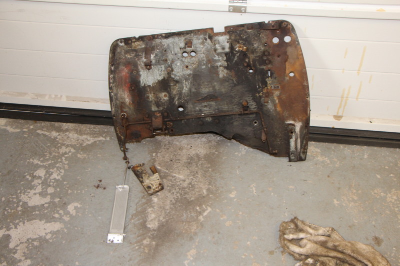
I had also taken off the aluminium panel that covers the dumb irons. This panel is in a very sorry state and I will look into fabricating a replacement. It is held in place using two bolts which also secure the badge bar cum starting handle support.
The radiator is held in place by two stays from the bulkhead, upper and lower hoses and a pair of bolts at the bottom. The stays and hoses are no problem. The bolts at the bottom of the radiator are above the oil cooler and almost impossible to get at. To improve access I removed the dynamo but that did not make it any easier.
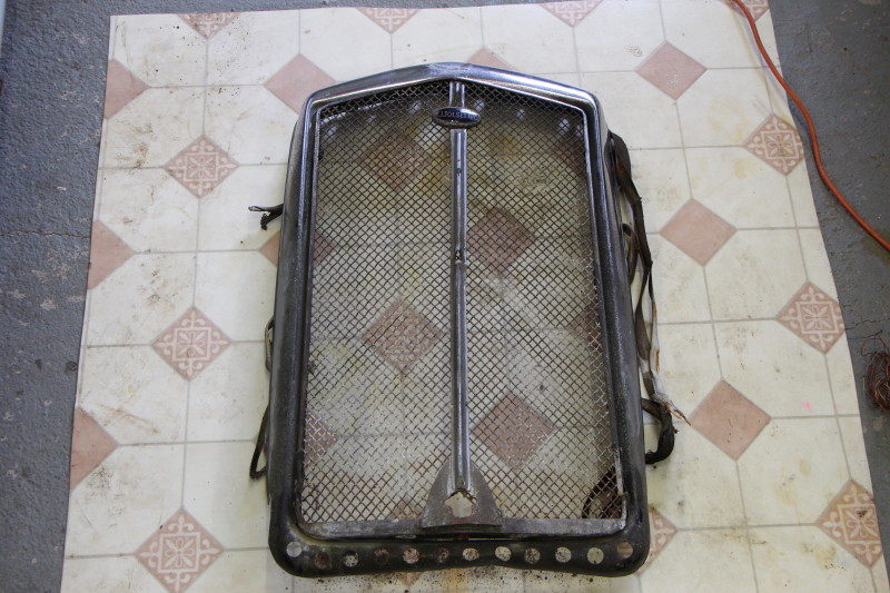
Time to get the oil cooler off. I had already drained the engine oil so disconnecting the flexible oil pipes was straightforward. Different size unions for flow and return should make future life easier. Two bolts going through the chassis cross member secure the cooler from the rear; good idea to take off the dynamo! However, what I did not know about were the two bolts going the chassis cross member into the top of the cooler. One thing leads to another and in order to get to these bolts I need to remove the radiator grill. This is held in place using 12 (yes 12!) 3/16" BSW countersunk slot head screws. Nightmare? Actually no. Thanks dad, they had been nicely greased and came out with no problem apart from losing one of the square nuts somewhere in the bottom of the radiator.
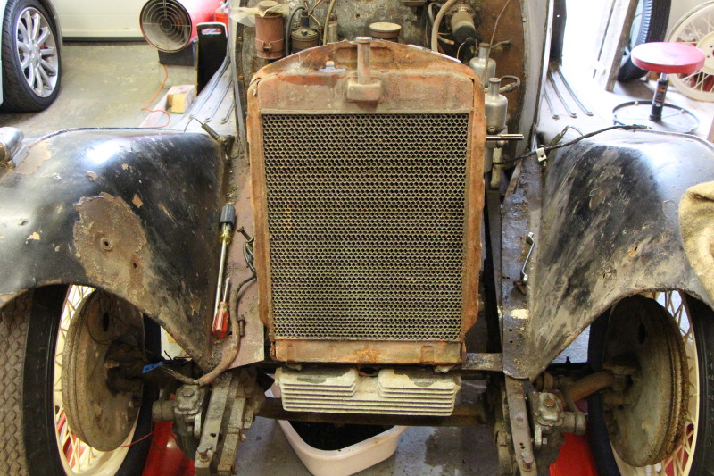
Anyway, I can now see the two offending bolts. They can still only be accessed using an open ended 1/4" BSW spanner. The right hand one was stiff but came undone eventually but because the bottom of the radiator is so close to the top of the oil cooler, the bolt cannot be removed. The left hand bolt put up a bit more of a struggle and I had to resort to forcing a 12mm spanner onto the bolt head; managed in the end though.
Now the fixings at the bottom of the radiator can be got at and removed. Finally the radiator is separated from the car. Phew!
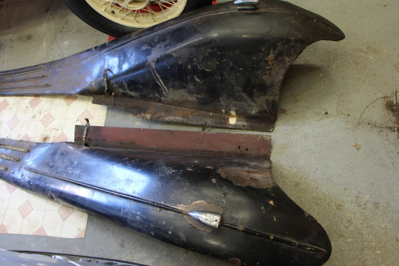
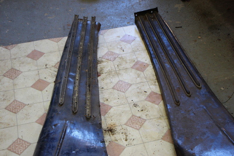
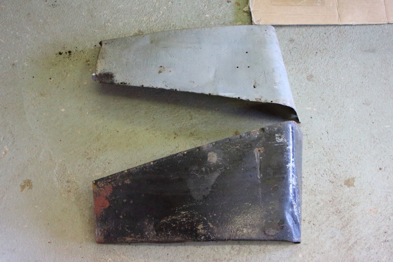
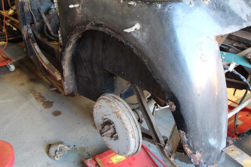
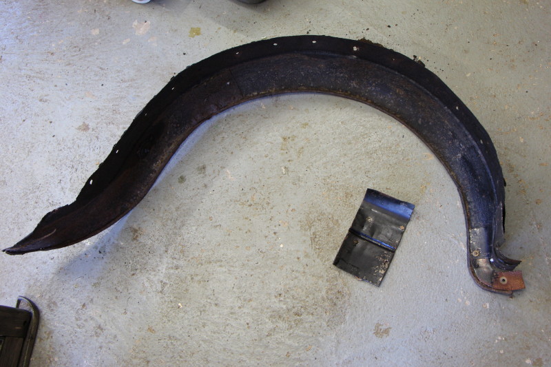
Next up - remove the front wings.
Not too difficult. Both wings were held on using a combination of nuts & bolts for the stays and pop rivets holding them to the rear wings.
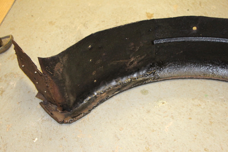
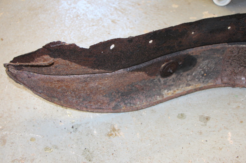
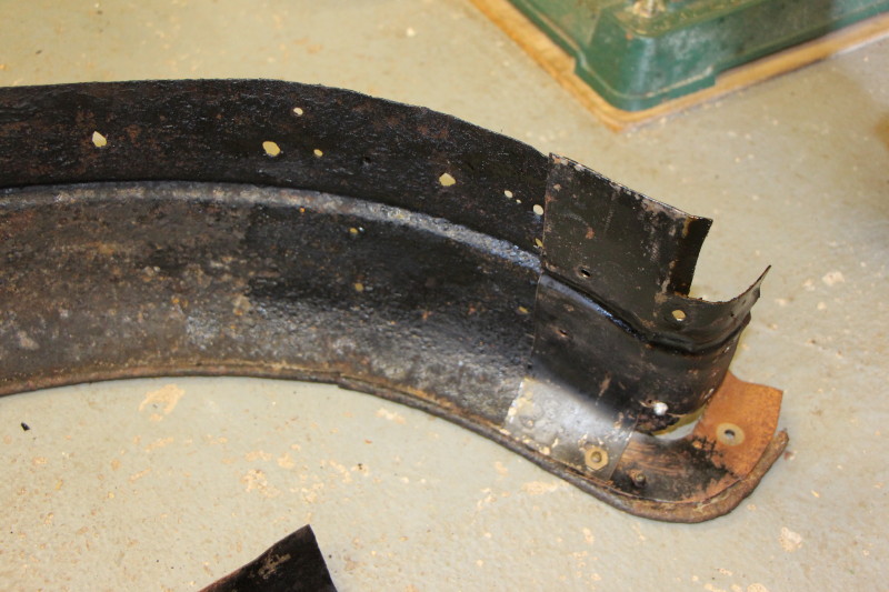
Both wings will need some attention to try and make them a bit tidier.
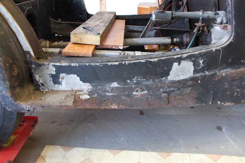
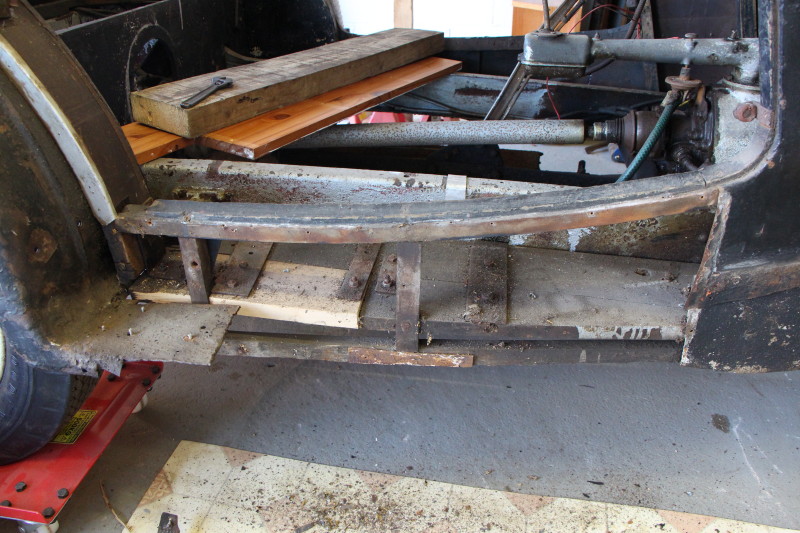
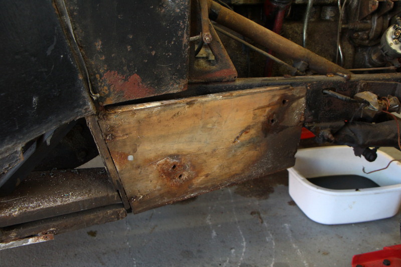
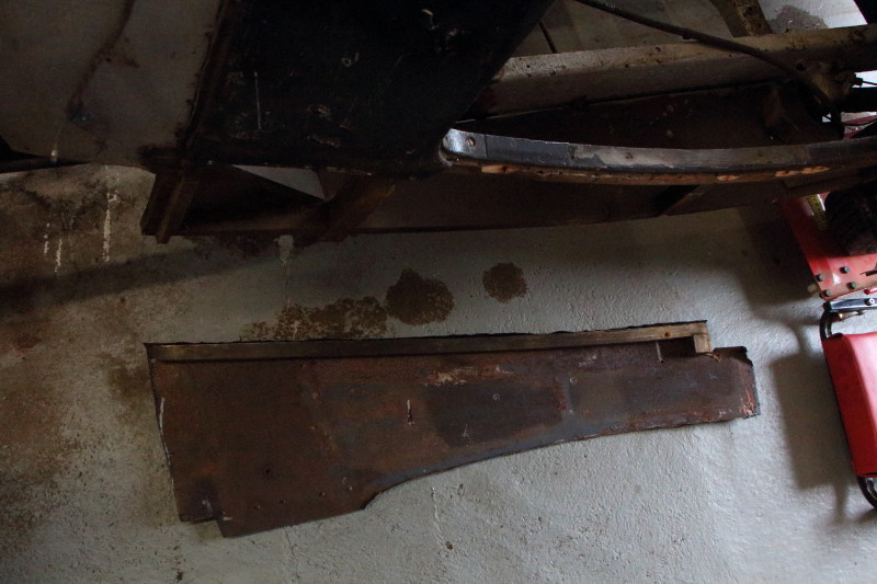
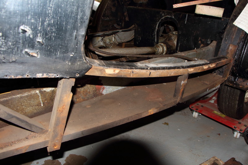
With the front wings and supports out of the way, I have access to the panels extending from the bulkhead, along underneath and just to the rear of the doors. These were removed without undue difficulty but directly under the doors the panel is folded over and tacked into place with small panel pins which made it a fiddly and time consuming job. However, in places bits basically just fell off.
The windscreen supports were also taken off.
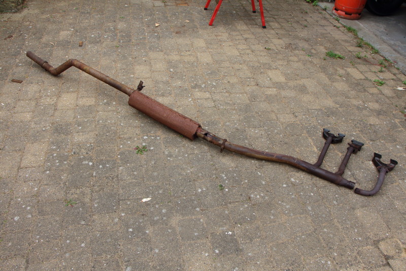
Now to get the exhaust system off.
The exhaust was not held on in many places; the exhaust manifolds at the front and a hanger just to the rear of the silencer.
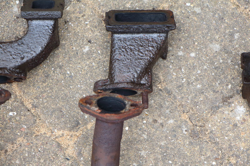
The hanger was removed and the exhaust system supported on a jack. The cylinder head manifold nuts were all removed which allowed the carburetors to be taken off and put to one side. I then had to unbolt the front exhaust pipe from the manifold casting and remove the front pipe before I could take the rest of the exhaust system off the car.
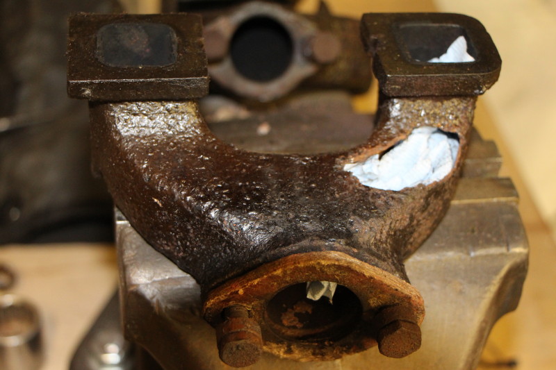
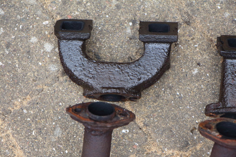
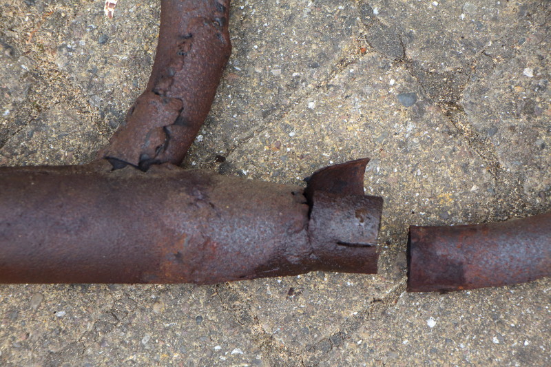
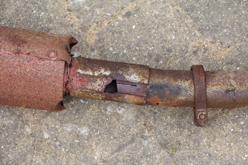
Unfortunately, nothing here is salvageable - this exhaust was home made and is no longer serviceable. Even worse is that one of the castings (the one nearest the radiator) has a massive hole in it. The other castings are very badly pitted and they all will need replacing. I only hope I can find a source for these parts.
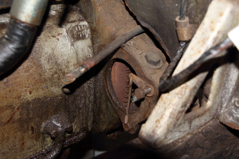
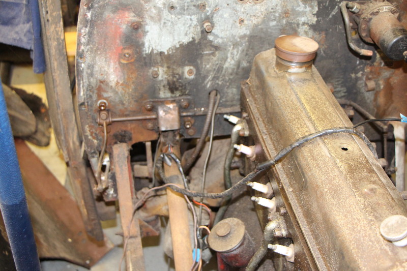
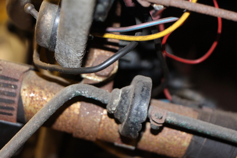
While I was in this area I also took the starter motor off, something I had attempted some time ago but was confounded by the exhaust system.
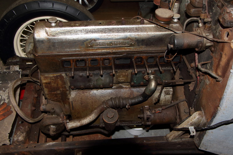
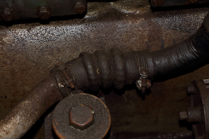
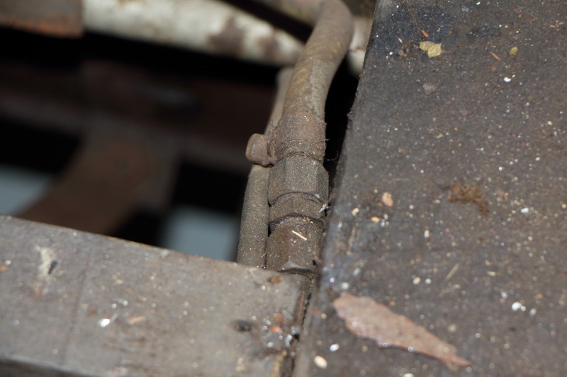
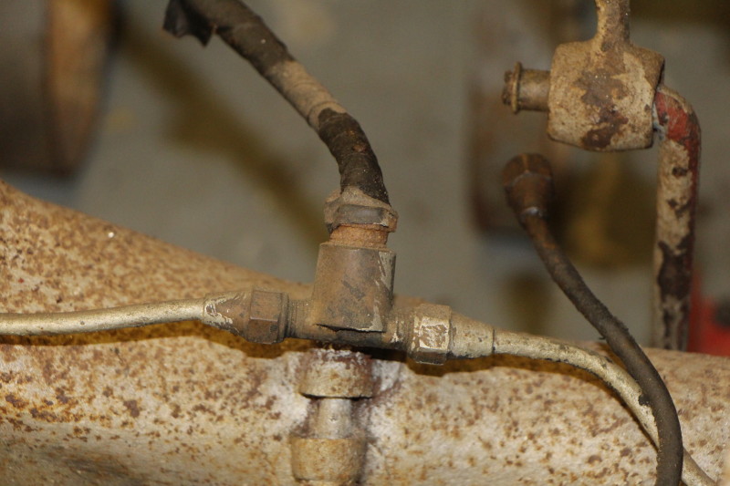
It is also apparent that something is not as it should be with the water pipe from the water pump.
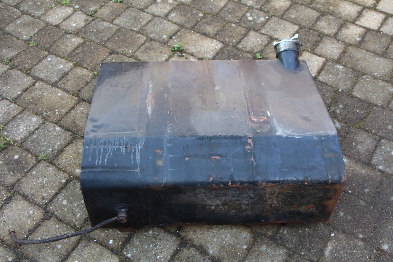
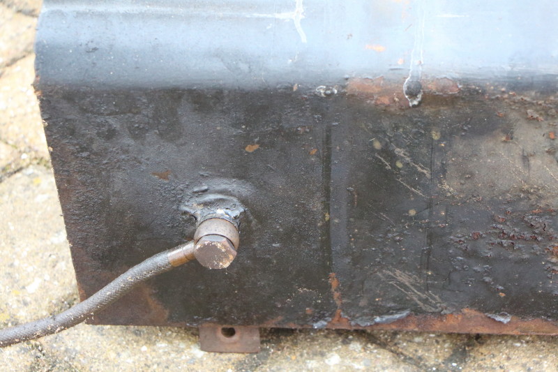
Next up is the petrol tank.
Number plate removed and put to one side still attached to the wiring harness.
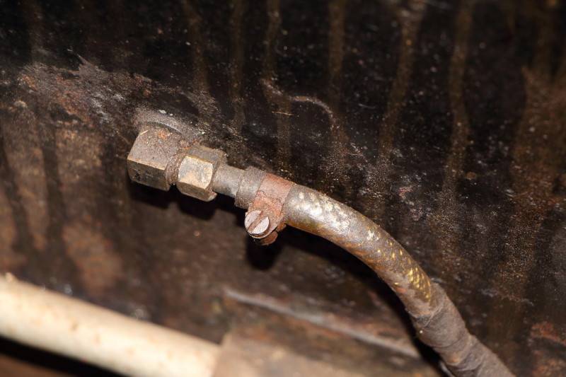
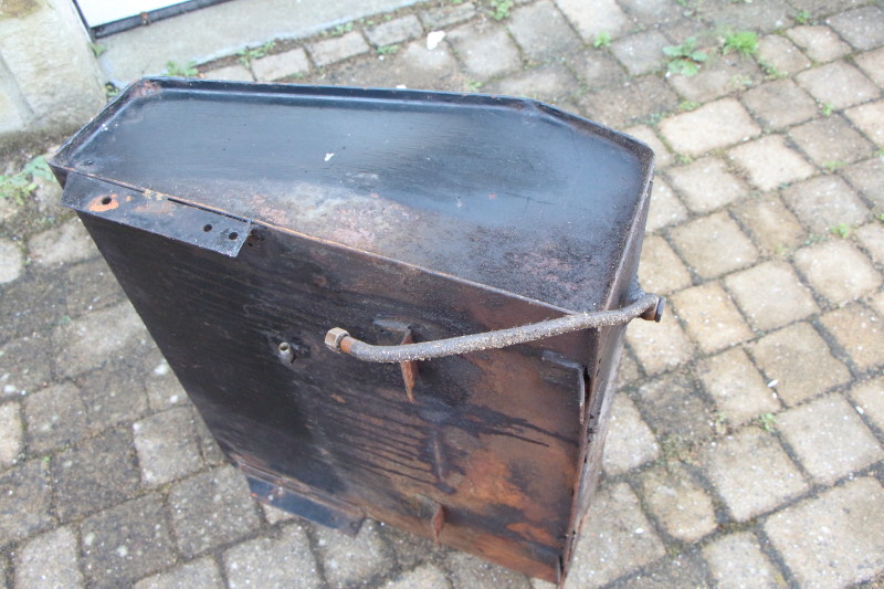
The tank has two pipes running to a tap on the dashboard that switches from main to reserve.These pipes are connected to the tank via hose pipes which can be disconnected quite easily.
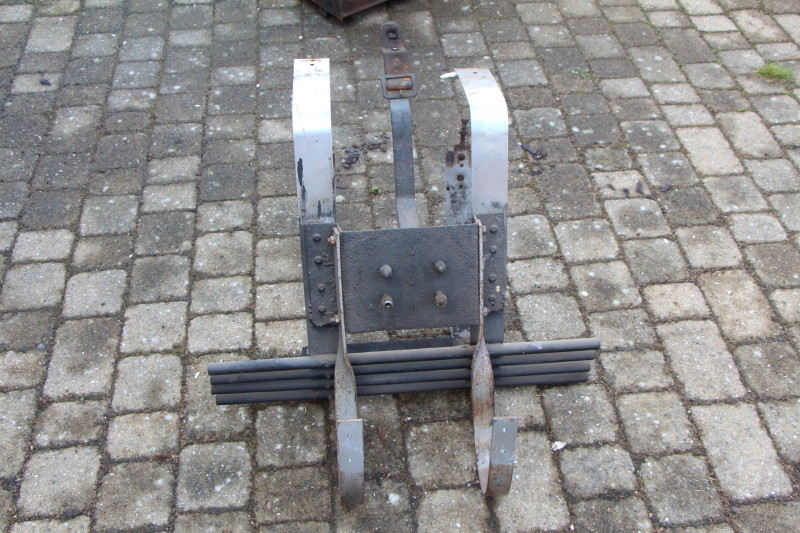
Then I removed the spare wheel hanger which is secured on two stainless straps that wrap around the tank and fasten to the bodywork and chassis. Another pair of straps and two brackets need to be released and this allows the tank to be lifted away. All pretty sraightforward.
Between the scuttle and the bulkhead there is a toolbox and two side panels. Again, panel pins and small screws were involved but with patience these items were removed.
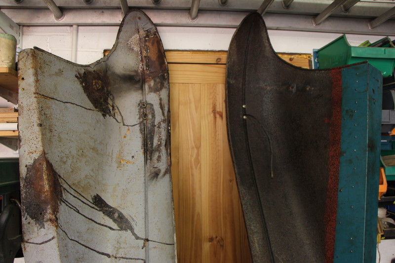
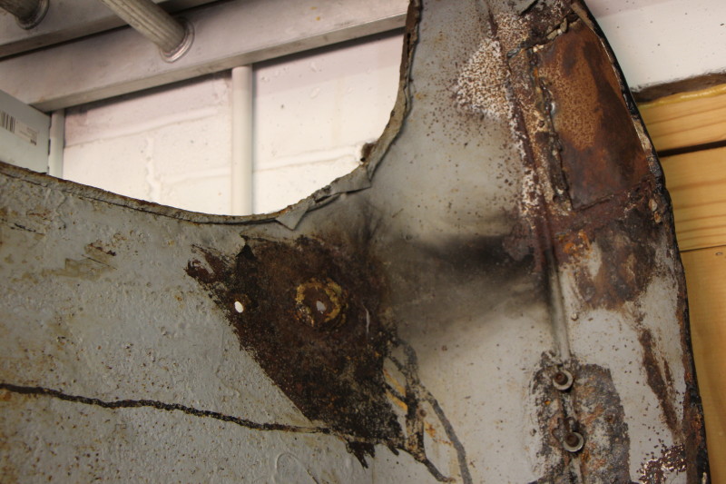
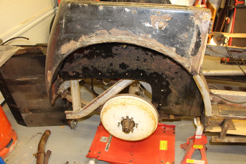
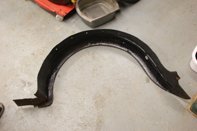
Now to get the rear wings off.
The driver's side wing was a little floppy to start with and sure enough, the woodscrews holding it in place were not very tight and looked quite new.
The near side was a different story. All the screws were rusty and difficult to remove. Most of them just sheared off. They were countersunk slotted woodscrews and I had to use some mole grips after levering the heads up a bit to gain purchase.
At this point it looks as though I could remove the body in two parts, a rear section from the back of the doors and a forward section from the front of the doors. The forward section carries the dashboard, scuttle and perhaps the bulkhead so, my next jobs are the wiring, steering column and dashboard.
The dash appears to be attached to the scuttle in three places, a pair of large screws accessible from the front on the left and right hand sides, and a third place in the middle at the rear of the dash.
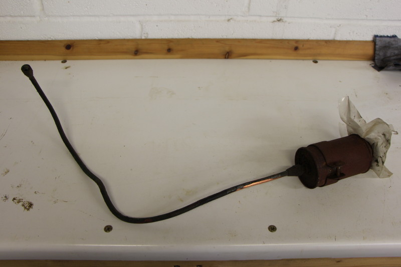
Choke control rod removed with part of the carburetor linkage from the engine side of the bulkhead after removing the knob and its locknut.
Cruise control was next to come off. This involved the removal of a spring clip clamped to the control rod just behind the dash. This was presumable meant to provide some friction to prevent the control rotating by itself. The clip is thin spring steel and was broken. Once removed the rod could be unscrewed from the accelerator mechanism and pulled through the metal pressure pad screwed to the back of the dash.
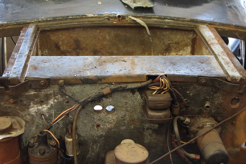
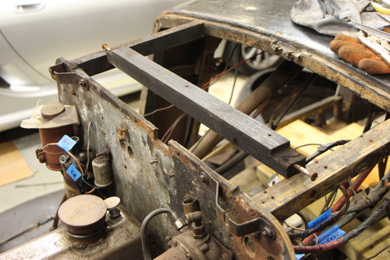
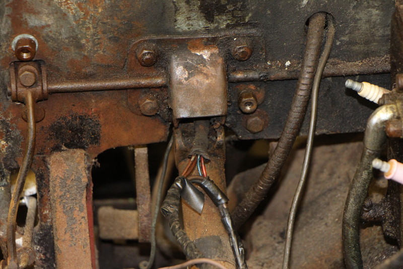
The cut-out relay and junction box was unscrewed from the bulkhead and after disconnecting a few wires from the petrol pump and ignition coil, the wiring harness could be bundled up ready to be removed when the dash comes off. While I was doing this I also removed a part of the frame which had been supporting the toolbox in the scuttle.
I then disconnected the wires to the HT coil and removed the indicator relay but left it connected to the harness. A single wire looped back through the scuttle to the horn and this was cut so it could be pulled back through the scuttle. This part of the wiring loom comes from the dash and through the scuttle just above the steering column.
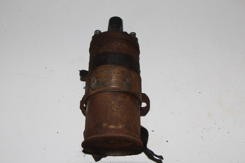
I also removed the HT coil and the brake reservoir tank and put them to one side.
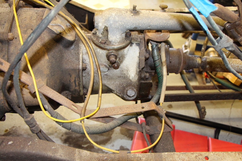
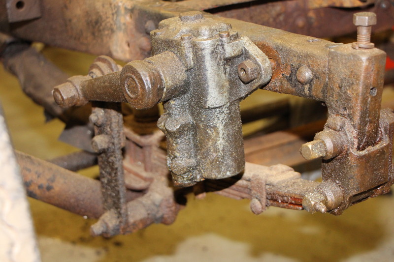
Steering column and steering box.
I had hoped to remove the column and box as a complete unit - this turned out to be a vain hope indeed.
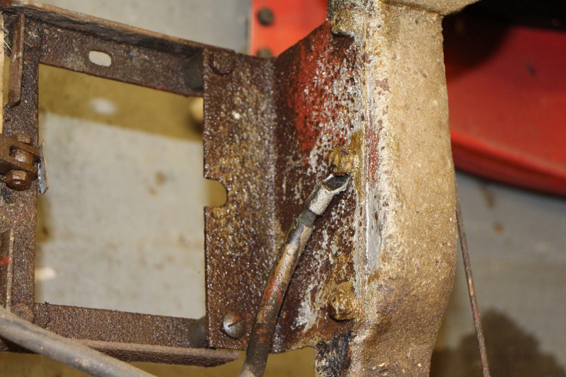
The advance / retard control runs down the side of the steering column so I disconnected this from the distributor and then removed the distributor to give better access to the box. The drag link was separated from the drop arm by unscrewing the plug in the end of the drag link and removing the spring and pressure pad which allows the ball joint to be slipped out. Put the bits back into the end of the drag link and tied it to the track rod to keep it out of the way.
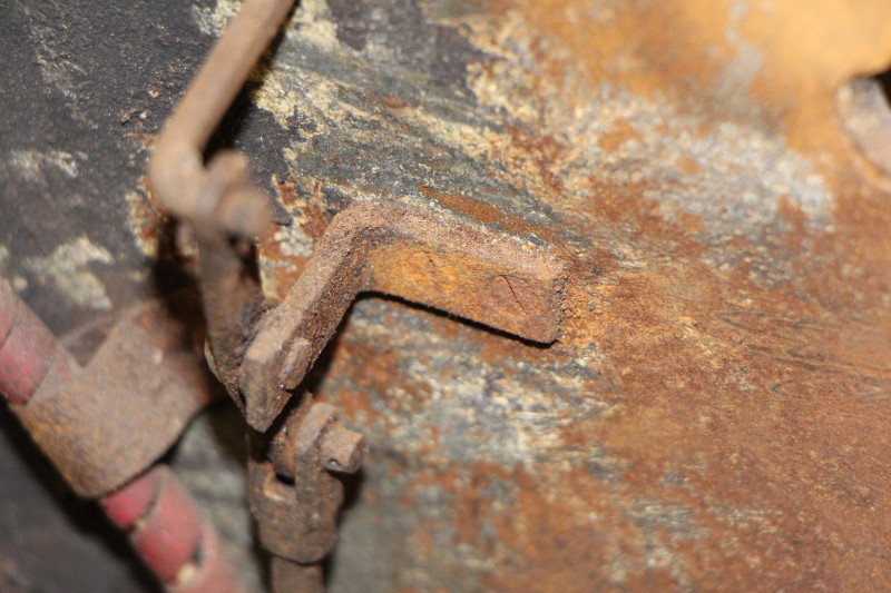
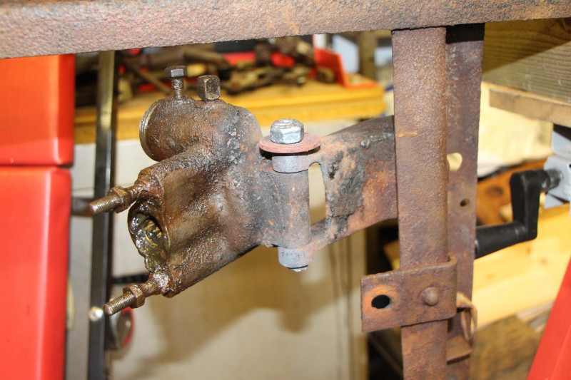
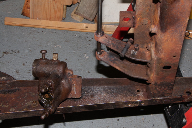
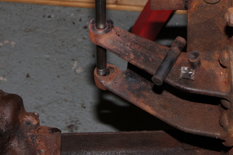
Unfastening the column was hindered slightly by an indicator stalk clamped to it. Getting that off resulted in a bag full of bits and a problem for the future. The column is clamped at the dashboard and the bulkhead and these are easily undone. The column was supported at the dashboard while I turned my attention to the last remaining fixing - a bolt securing the steering box between two lugs of a bracket riveted to a chassis cross member. This bolt refuses to move. The nut is off but the head was already completely rounded off. Mole grips, penetrating fluid and gentle heat (quite oily round here) did nothing. The engine prevented me from hitting the end of the bolt so I removed the column along with its worm and left the box till later.
Dashboard.
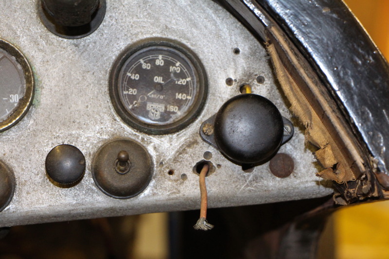
Not much left to do now. The wiring harness to the front is bundled up. The oil and water temperature sensors have been pushed back through holes in the bulkhead. The oil pressure pipe has been disconnected both at the sump and at the gauge and put aside. Rev counter and speedo cables dealt with albeit with the rev counter still attached (cable does not want to unscrew from the gauge). It was easier to disconnect the wires going to the rear of the car so I did just that and bundled it up with the rear light/number plate assembly. All that was then necessary was to remove two screws (the middle one was missing) and remove the dashboard.
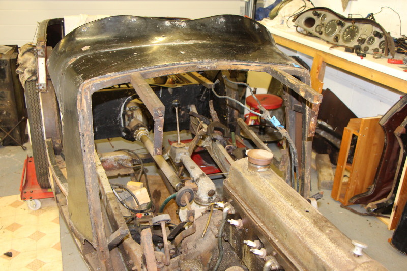
Bulkhead.
Most things have been removed, just the petrol pump left. Two woodscrews and two corner brackets hold the top of the bulkhead can be removed once the radiator stay brackets are rotated out of the way. Then from inside the car remove the two brackets that support the toe-board. Then unbolt the bulkhead from the corner brackets bolted to the chassis. The bulkhead, complete with throttle pedal and associated bits, can be lifted away.
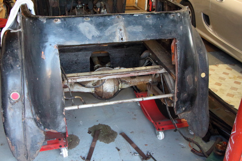
Body and frame.
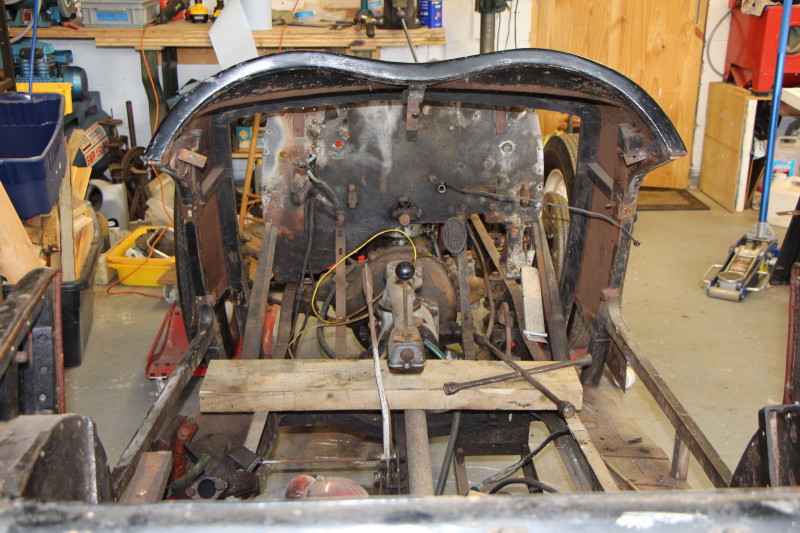
There was very little holding the front and rear halves of the body together. A couple of brackets screwed into the rear wheel arches, that's all. After they were removed the rear of the body was unbolted from a chassis cross-member and lifted away.
The front section just needed to be unbolted from the outriggers below where the doors go and that too could be lifted away.
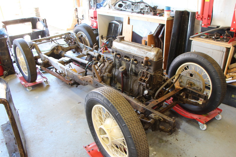
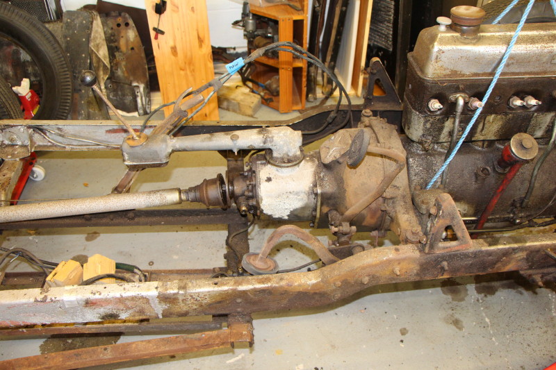
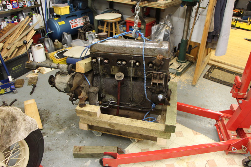
Engine.
The engine and gearbox are now totally exposed and can be removed with relative ease. Remove the starter switch and associated cables, the toe-board brackets. Disconnect the prop shaft universal joint then unbolt the front and rear engine mountings and it can be lifted out. There was a brief digression while I put together an engine stand on wheels end then get the crane out to extract the engine and gearbox.
As the engine is now out of the way, I had another look at the steering box. Removed the drop arm (weird shape!). Took off the box's lid and removed the wheel. Wiped out as much grease as I could and got the blowlamp out again. Still no joy. Swapped my soft headed hammer for my 2lb ball peen. Nothing. I can see where this is heading; one of the many skills I have failed to master - drilling out a bolt, usually sheared at a threaded portion. I always seem to get the hole drilled off-centre and off-axis. Anyway, enough for now. Time to take off the axles and springs.
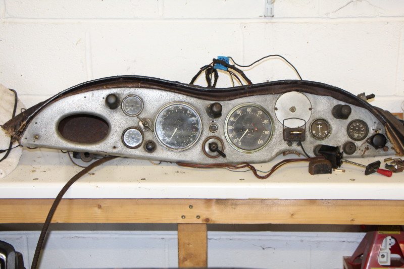
Dashboard. Slight change - strip the dashboard and have a look at the instruments because there is the 'Classics in Corbridge' event coming up shortly and I might see something I need.
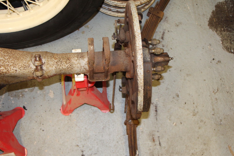
Axles and springs.
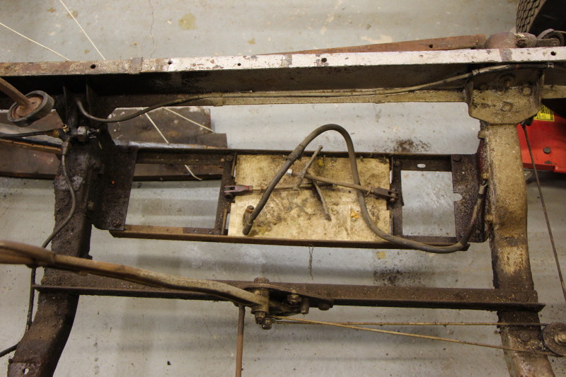
The rear axle still has a few things attached which need to be removed first: brake pipes; handbrake cables; prop shaft and near side shock absorber, to name but four. The battery carrier also gets taken off at this point.
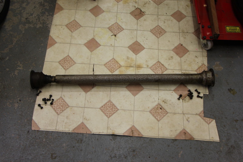
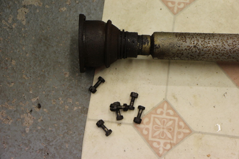
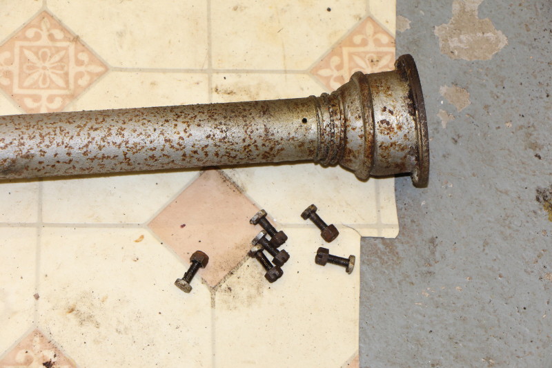
The prop shaft was removed first. The shaft looks reversible but I labelled it anyway The bolts (6 at each end) have special heads and are cross-drilled for a wire nut retainer so these need to be looked after.
The battery cradle was unbolted next to make it easier to step 'through' the chassis.
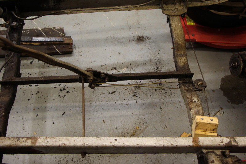
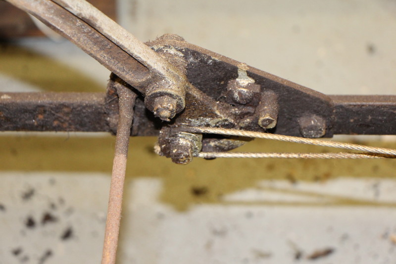
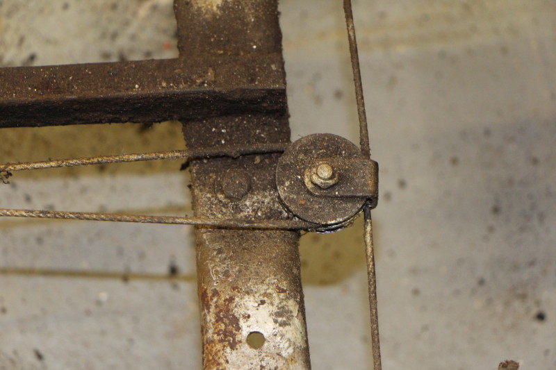
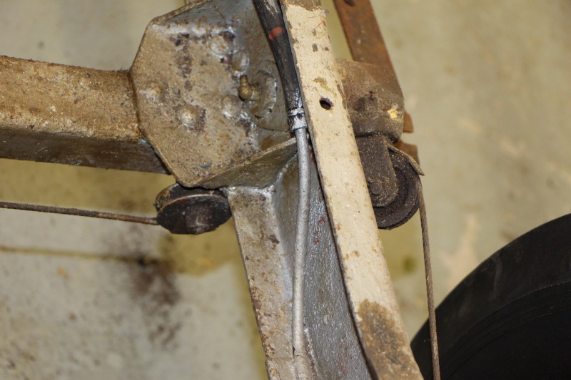
The hand brake cable is just one length of wire rope which loops through the brake adjusters and goes via a system of pulleys to the handbrake lever. The terminating loops are maintained using small u-clamps which I took off first. Each half of the cable goes around three pulleys each of which has a cable guide. The cable was kinked and frayed at the ends and I found it easier to remove the pulleys with the cable still attached. Finally the handbrake lever was unbolted from its supports which were also taken off.
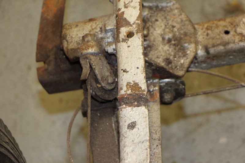
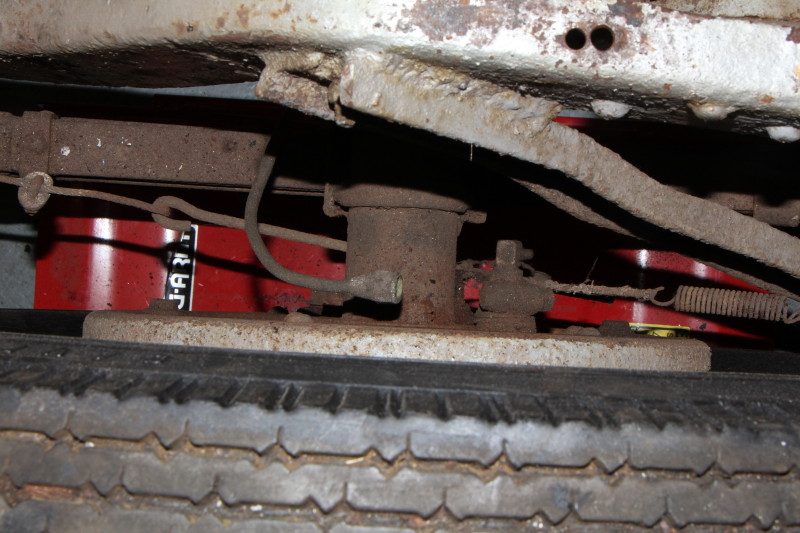
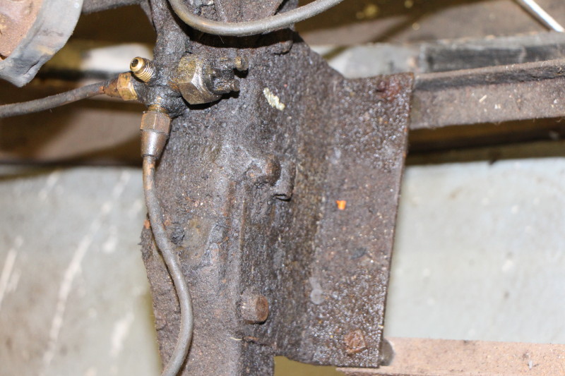
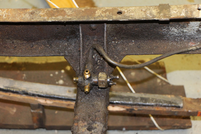
The brake pipes are next and some still have brake fluid in. Note to self - brake fluid is an effective paint stripper even on my special garage floor paint. Special clips hold the brake and petrol pipes in place along the chassis and these are still effective. There are three flexible pipes, one to each of the front brake drums and one to a T-junction mounted to the left of the banjo on the rear axle. The foot brake pedal and its support bracket were also removed.
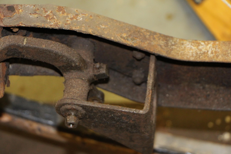
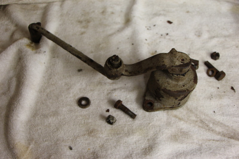
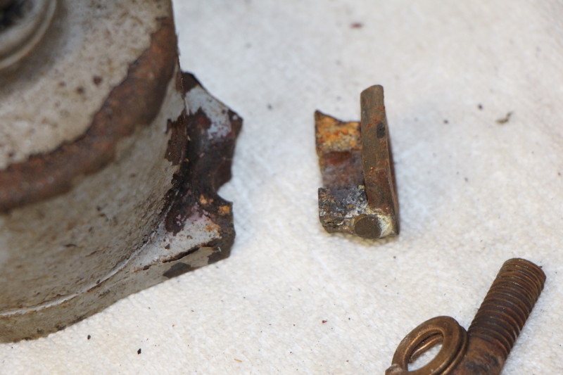
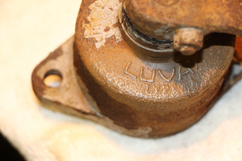
The near side shock absorber was the next target. This came off quite easily although one of the mounting lugs had fractured and a repair had been attempted. Also interesting to note that it had been mounted with the filler plug at the bottom. No idea why. The off side one I found in a box of bits so they are now together.
I then removed the front shock absorbers and the two corner brackets that held the bulkead.
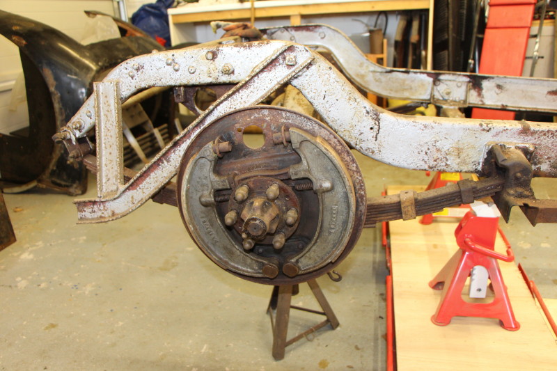
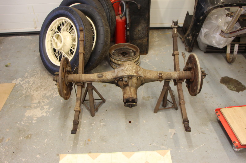
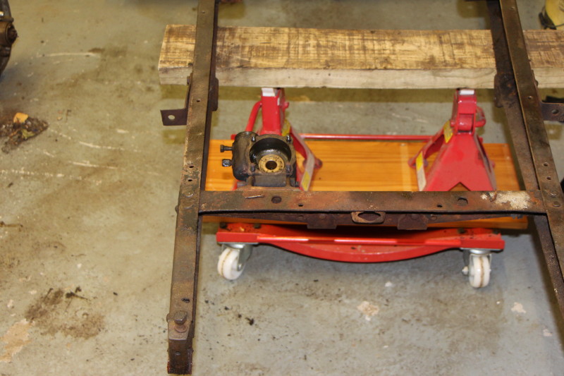
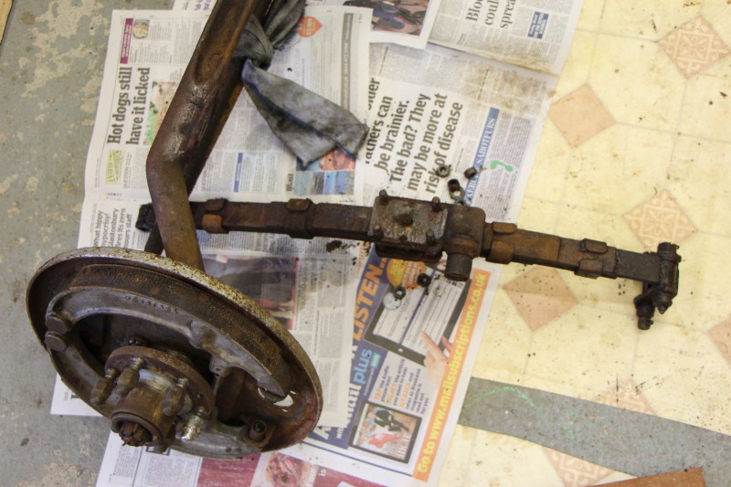
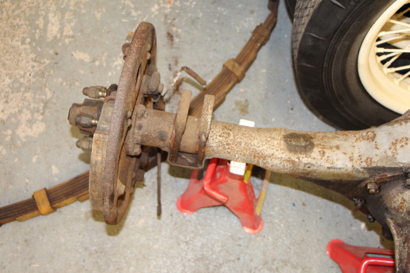
I am now down to a rolling chassis so I need to support it while I remove the wheels, brake drums and the axles themselves. The axles were released by simply removing the shackle pins that connected the springs to the chassis. The rear axle complete with springs was put on a pair of axle stands.
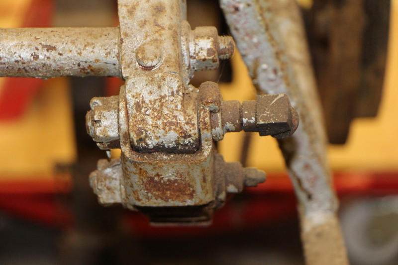
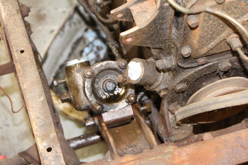
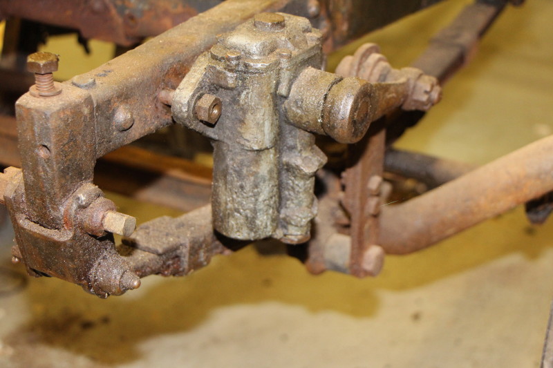
Steering box.
The time has come to face my nemesis. I have no more excuses. The box is as accessible as it will ever be.
Firstly, warm it up with the blowlamp and hit it. Nothing happens.
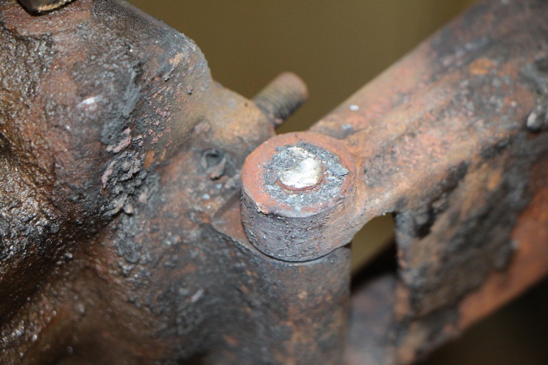
Get the oxy-acetylene kit out and weld a nut onto the rounded head of the bolt hoping that the thermal shock of doing that will release the bolt at least partly. Big spanner. Sheared it off. I kind of expected that to happen.
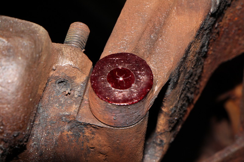
File the sheared end flush with the lug, centre pop it and start drilling. Only went as deep as the thickness of the lug. Gradually increase the size of the drill bit until I just break through to the lug hole (I have a set of drill bits in 0.1mm increments). Using a steel pin punch I give it a decent thump. It moved! I hit it a few more times and it went in a mm or so. It was only then that I checked the other side of the bracket and found that the other lug was bending.
My first real "oh s**t" moment.
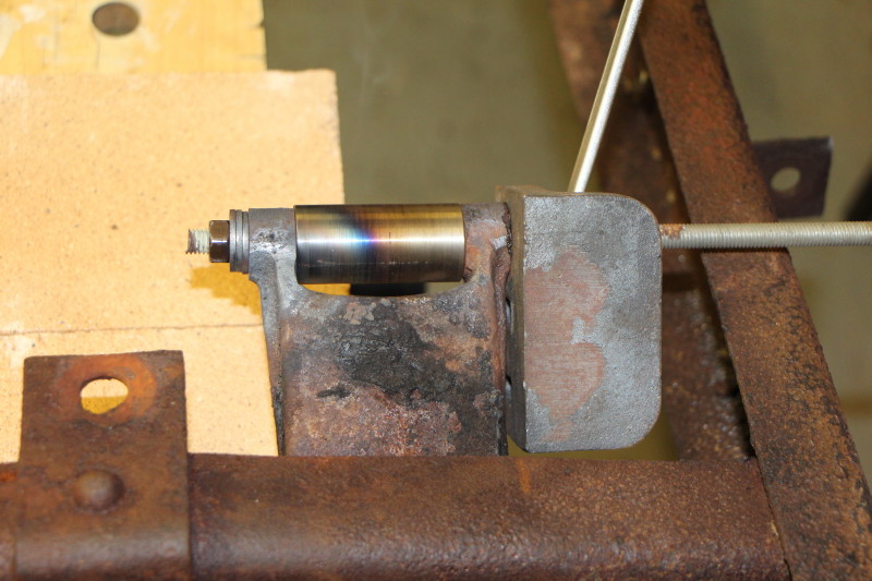
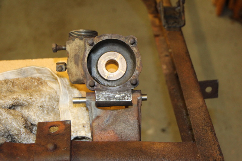
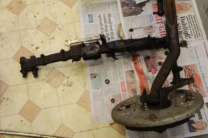
Once I refocussed I found that the gap was big enough to get a hacksaw blade in and I could sever the other, threaded, end of the bolt. With a little twist the steering box was off. The remains of the bolt in the steering box and the lug were easily drifted out. Now I had to repair the damage.
I machined a spacer to the width of the steering box mounting (2") with parallel end faces. A piece of studding was used to bolt the spacer in place between the lugs. Got the bent lug hot using my oxy-acetylene kit and tightened up the bolt. That seems to have pulled the lug back into place except for a slight misalignment. A 3/8" bolt will fit, though.
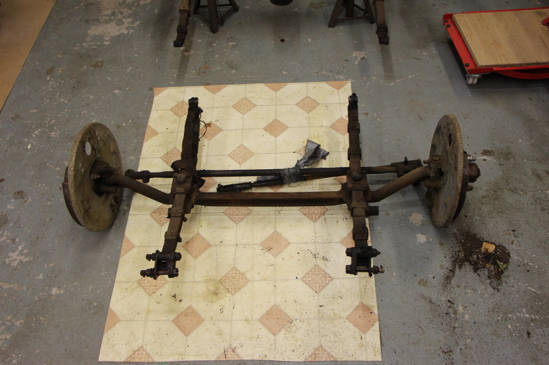
Final chapter of this disassembly is draining the diff and removing the springs from their axles.
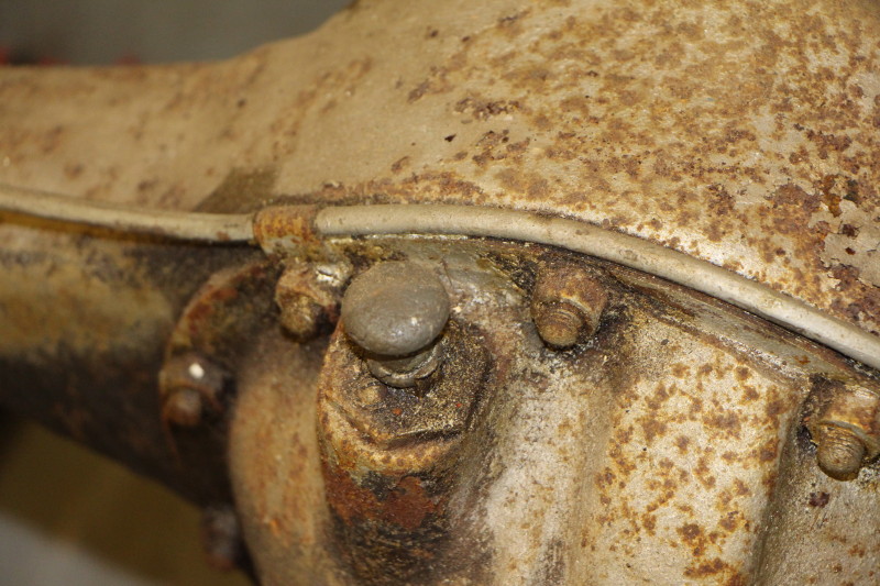
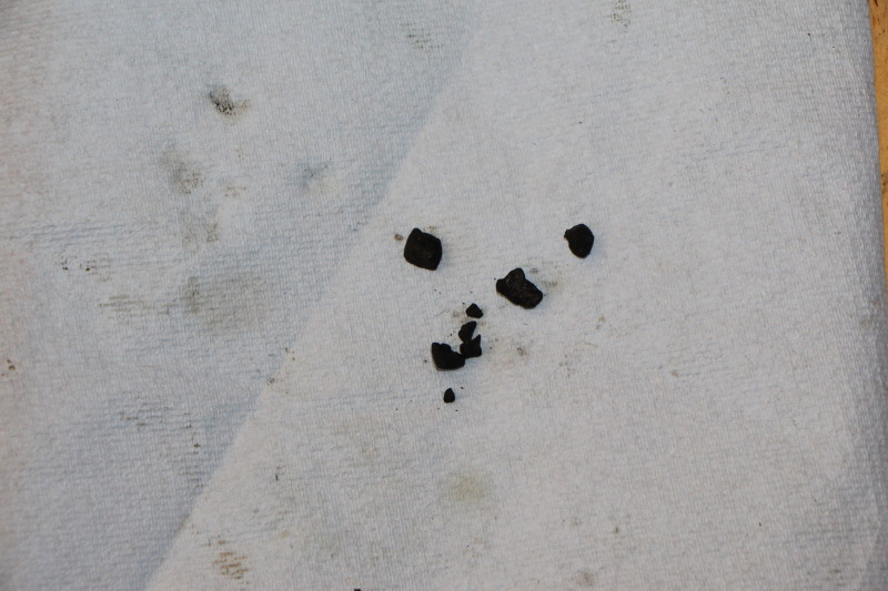
Plenty of oil in the diff (Hypoy 90?) but found a few lumps in the drain plug which has quite a deep recess. A quick investigation revealed that they were non-magnetic so hopefully nothing too serious.
All the nuts holding the springs came off without difficulty but the rear springs do not look to be in good condition.
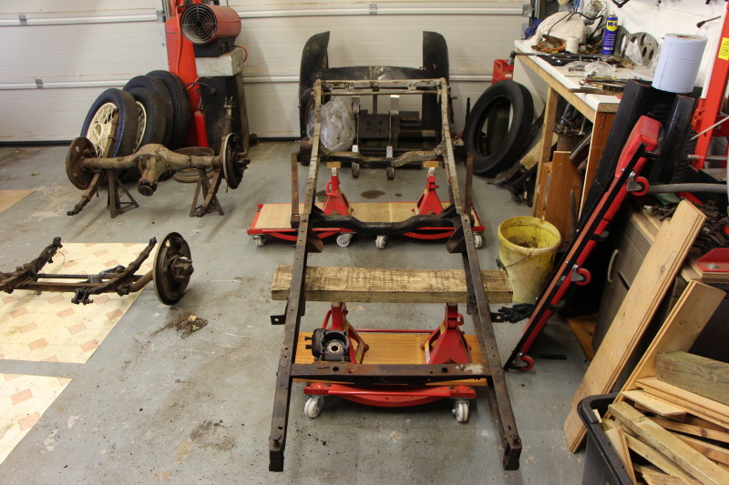
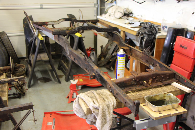
That completes the first phase of the restoration project.
What happens next? Clean up the chassis and make sure it is still reusable. Check and adjust the alignment. Make any repairs necessary. Paint.
After that it is simply a reversal of the disassembly process. Simple!
Oh, and don't forget to turn it around so that I can drive the car out of the garage rather than reverse it.
That concludes this part of the account, further work will be detailed in the various sub-categories which have remained empty - until now.